background image

SCAN EXAM 

7

2. Intraoral imaging plate unit

2.3 Display symbols and what they mean

During use symbols and animations will ap-

pear on the unit display. These:

-  indicate the status of the unit

-  help you to operate the unit correctly

-  show user mistakes and corrective actions

-  display error codes

-  display a preview image 


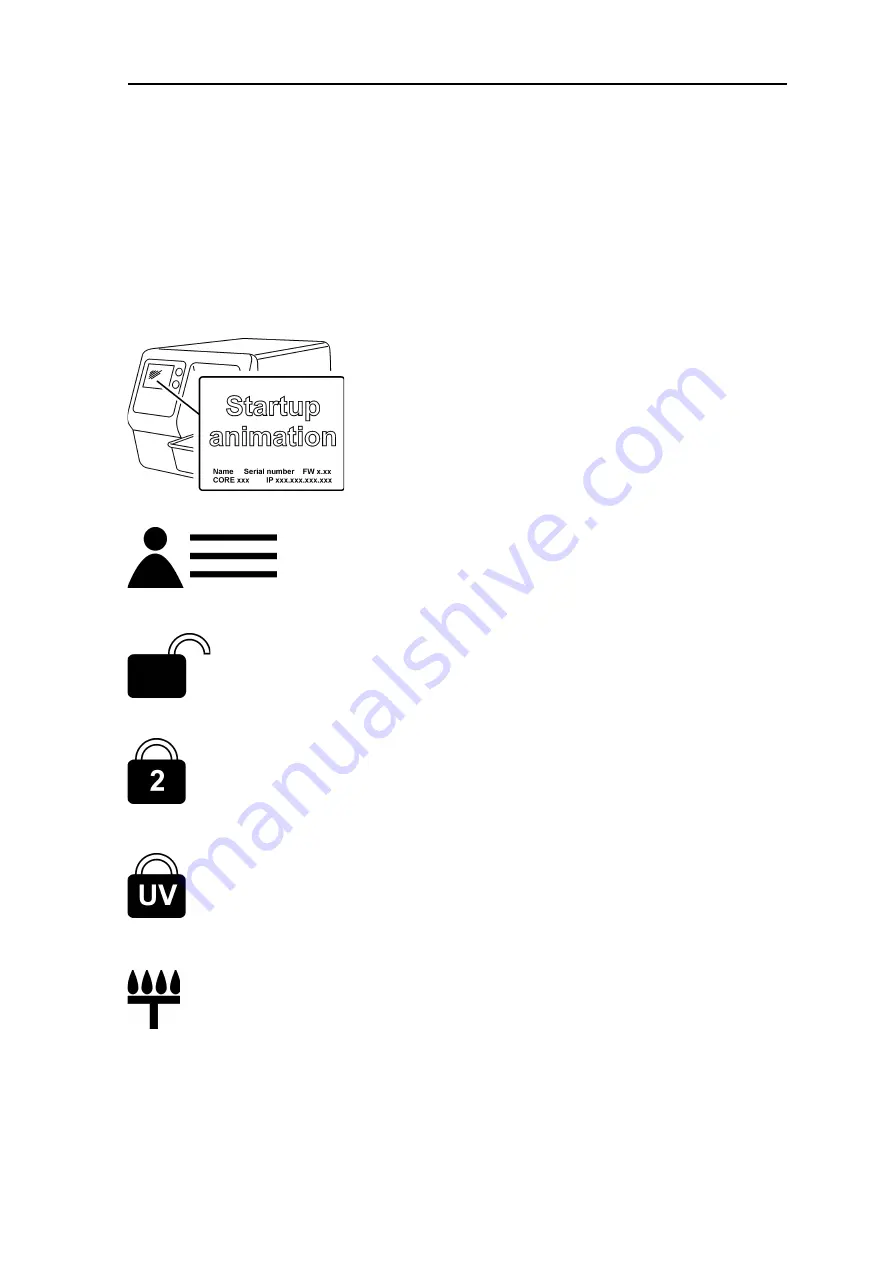
The main symbols are:

Startup

During startup the unit serial number, IP ad-

dress and other information will appear on 

the unit display.

Patient name

Indicates a patient card is open. The patient’s 

name is shown on the unit display.

Express Share wait

Express Share con

fi

 guration. The unit is not 

reserved by any PC in the system.

Express Share reservation

Express Share con

fi

 guration. The unit has 

been reserved by a PC (e.g. PC number 2).

UV disinfection in progress

The system is carrying out automatic UV dis-

infection cycle. Remaining cycle time will be 

displayed.

Comfort Occlusal™ 4C mode

System in occlusal projection imaging mode.

Summary of Contents for SCAN EXAM

Page 1: ...SCAN EXAM Digital imaging plate scanner User Manual ENGLISH 215948 rev 1 0 805 5059...

Page 2: ......

Page 3: ...yright laws the documentation may not be copied photocopied reproduced translated or reduced to any electronic medium or machine readable form in whole or part without the prior written permission of...

Page 4: ...IV User manual 215948...

Page 5: ...an IP for exposure 13 3 4 Imaging plate holders 15 3 5 Taking an exposure 16 3 6 Reading an imaging plate 18 Single user configuration 18 Express Share configuration 22 3 7 Removing IPs from the plat...

Page 6: ...6 Symbols that may appear on the unit and accessories 34 7 Warnings and precautions 36 Appendix A Technical Specifications A 1 A 1 Unit A 1 A 2 Imaging Plates and hygiene bags A 2 A 3 Main dimensions...

Page 7: ...User manual 215948 VII...

Page 8: ...VIII User manual 215948...

Page 9: ...tware A local area network LAN cable not supplied will be required if the system is to be used in a network The unit is a laser scanning device designed to automatically read reusable KaVo Kerr dental...

Page 10: ...llation Positioning the unit Do not position the unit in direct sunlight or near bright light Sunlight or bright light must not be allowed to shine directly on the unit door into which the IPs are ins...

Page 11: ...ce between the patient and the PC is 1 5 m 4 5 ft The minimum vertical distance between the patient and the PC is 2 5 m 6 5 ft Other devices DO NOT connect any other devices to the unit or the PC conn...

Page 12: ...4 SCAN EXAM 2 Intraoral imaging plate unit 2 Intraoral imaging plate unit 2 1 Main parts and controls...

Page 13: ...s Equivalent to film sizes 0 1 2 and 3 IDOT version IDOT IPs optional have individual identification codes that appear on the images IDOT aids quality assurance by making it possible to identify the p...

Page 14: ...ags supplied by the manufacturer of the unit or the manufac turer s authorized distributors The manufacturer will not be held responsi ble for problems caused by using accessories from other manufactu...

Page 15: ...rial number IP ad dress and other information will appear on the unit display Patient name Indicates a patient card is open The patient s name is shown on the unit display Express Share wait Express S...

Page 16: ...cclusal 4C mode System in occlusal projection imaging mode insert second size 3 IP Unit door Protective cover and imaging plate Yellow remove protective cover Imaging plate Yellow wrong way round rota...

Page 17: ...Unit in UV disinfection mode the remaining elapsed disinfection time is shown Unit in erasing mode Check Something wrong or take alternative action Dental imaging software Software not open not ready...

Page 18: ...10 SCAN EXAM 2 Intraoral imaging plate unit Rotate Error state and error number Check documentation supplied with the unit Unit in service mode Service technicians only...

Page 19: ...the IPs ensures the best image quality and maxi mum service life of the IPs Refer to section 4 Handling and care of imaging plates IMPORTANT NOTICE If you are using the system for the first time check...

Page 20: ...uring which the IP carrier will slide out of the unit door When the status light turns green and ready animation indicating IP insertion appears on the unit display the unit is ready to use in the rea...

Page 21: ...l projection expo sure refer to section 3 12 Taking an occlu sal projection image and to the separate instructions supplied with the Comfort Occlusal 4C kit 1 Place the IP you wish to use onto a pro t...

Page 22: ...bag 5 Peel off the cover paper from the seal ing tape and then fold the flap along the pre formed line over and onto the sealing tape 6 Press and slide your thumb along the tape to ensure that the fla...

Page 23: ...and thus distortion is eliminated the IP cannot move in relation to the X ray unit images are standardized and reproducible there is no overlapping nor cone cut off IP wear and tear is minimized image...

Page 24: ...images even if the exposure values differ consid erably from the optimum values In most cases the same exposure values can be used for virtually all imaging purposes For normal everyday use select the...

Page 25: ...ry incisor 0 20 0 12 0 40 0 25 0 10 0 06 0 20 0 12 Maxillary cuspid 0 20 0 12 0 40 0 25 0 10 0 06 0 20 0 12 Maxillary molar 0 30 0 20 0 63 0 40 0 16 0 10 0 33 0 20 Occlusal 0 25 0 16 0 50 0 32 0 12 0...

Page 26: ...e instructions supplied with the Comfort Occlusal 4C kit CAUTION For optimum image quality the exposed IP must be read as soon as possible after expo sure If the exposed IP is not read immedi ately af...

Page 27: ...re moved the unit detects that the IP is in the unit door and will switch from the standby state to the ready state ready to use and automatically slide the IP into the unit CAUTION If the IP does not...

Page 28: ...supplied with the dental imaging software you are using CAUTION If the metal disk on the rear of the IP can be seen on the digital image it indicates that the IP was exposed from the wrong side CAUTIO...

Page 29: ...not ejected into the plate collector When the IP is in the plate carrier the IP is easier to handle and stricter hygiene measures can be observed Refer to Appendix B 3 4 Workflow page After the IP has...

Page 30: ...the unit and it can now be used to read an image NOTICE If the device does not become ready after it has been selected different icon colors symbols indicate the status of the device YELLOW The device...

Page 31: ...time store them in their stor age box 3 8 Standby mode If no IP is inserted into the unit within a cer tain period of time the unit will beep several times and the status light will start to flash Whe...

Page 32: ...t caused the com munication failure When the connection between the unit and the PC is re estab lished the last processed image is auto matically transferred to the PC 2 PC If the image is not automat...

Page 33: ...es itself off If you wish to switch the unit off before the UV disinfection cycle is complete press and hold down the power on off key again 4 seconds and the unit will shutdown If you wish to return...

Page 34: ...it is now in the erase mode 2 Hold the IP by its edges or use a protec tive cover and position it so that the side with the metal disk the back is on the right Insert the IP into the unit door remove...

Page 35: ...images 1 PC Select occlusal from Device set tings Occlusal or Setup Scanner Occlusal see section B 3 7 Occlusal page depending on the software you are using 2 Place two size 3 IPs into their correspon...

Page 36: ...nit can still to be used if the UV dis infecting lamp has blown Press the start key to continue using the unit If you wish to disable UV disinfection com pletely see section B 3 6 Hygiene page PC If t...

Page 37: ...4 2 Handling Handle IPs in the same way as you would handle CDs or DVDs Hold IPs by their edges using your finger tips Protect the sensitive side of the IP from scratches wear and mechanical damage st...

Page 38: ...ment For stubborn marks and stains that can not be be removed using the microfibre cloth use 70 96 ethanol 70 96 EtOH 30 4 DI WATER or ethanol anhydride Wipe the IP as described above and then wipe dr...

Page 39: ...er the IP has been properly cleaned the IP is mechanically damaged scratched or badly bent 4 6 Disposal IPs must be disposed of in accordance with all local national and international regula tions reg...

Page 40: ...oistened with water Never use solvents or abrasive cleaners to clean the unit Never use unfamiliar or un tested cleaning agents If you are not sure what the cleaning agent contains DO NOT use it If yo...

Page 41: ...nctions in any way it must only be repaired by service per sonnel authorized by the manufacturer of the unit 5 5 Disposal At the end of the useful working life of the unit and or its accessories make...

Page 42: ...facturer Date of manufacture Catalogue number Serial number Batch code DANGEROUS VOLTAGE LASER RADIATION ULTRAVIOLET RADIATION Operating instructions Refer to operating instructions for more informati...

Page 43: ...nd or the production line where they were manufactured conform to the Russian Safety Standards USA only Caution Federal law restricts this device to sale by or on the order of a dentist Do not reuse R...

Page 44: ...reading an imaging plate This unit must only be used to read image plates supplied by the manufacturer and must not be used for any other purpose NEVER use imaging plates protective covers or hygiene...

Page 45: ...dard The PC and any other external device s connected to the system outside the patient area must meet the IEC 60950 standard minimum requirement Devices that do not meet the IEC 60950 standard must n...

Page 46: ...in case of connection lost during image processing Image is stored in unit memory until it has been transferred to PC Unit cannot be turned off in that case When network is operational again image is...

Page 47: ...exposed to the imaging plates from the intraoral complex of the skull Laser Safety Classification CLASS 1 LASER PRODUCT EN 60825 1 2007 Dimensions H x W x D 196 mm x 215 mm x 382mm 7 7in x 8 5in x 15...

Page 48: ...supplied instructions The use of genuine hygiene accessories protective covers and hygiene bags will extend the service life of the imaging plates Disposal Imaging plates are industrial waste and mus...

Page 49: ...SCAN EXAM A 3 A Technical Specifications A 3 Main dimensions...

Page 50: ...gnetic environment guidance 5 HPLVVLRQV 635 URXS 7KH H DP XVHV 5 HQHUJ RQO IRU LWV LQWHUQDO IXQFWLRQ 7KHUHIRUH LWV 5 HPLVVLRQV DUH YHU ORZ DQG DUH QRW OLNHO WR FDXVH DQ LQWHUIHUHQFH LQ QHDUE HOHFWURQL...

Page 51: ...D W SLFDO FRPPHUFLDO RU KRVSLWDO HQYLURQPHQW 6XUJH r N9 GLIIHUHQWLDO PRGH r N9 GLIIHUHQWLDO PRGH 0DLQV SRZHU TXDOLW VKRXOG EH WKDW RI D W SLFDO FRPPHUFLDO RU KRVSLWDO HQYLURQPHQW 9ROWDJH GLSV VKRUW L...

Page 52: ...WHUPLQHG E DQ HOHFWURPDJQHWLF VLWH VXUYH D VKRXOG EH OHVV WKDQ WKH FRPSOLDQFH OHYHO LQ HDFK IUHTXHQF UDQJH E QWHUIHUHQFH PD RFFXU LQ WKH YLFLQLW RI HTXLSPHQW PDUNHG ZLWK WKH IROORZLQJ V PERO 127 W 0 D...

Page 53: ...HU RI WKH FRPPXQLFDWLRQV HTXLSPHQW 5DWHG PD LPXP RXWSXW SRZHU RI WUDQVPLWWHU 6HSDUDWLRQ GLVWDQFH DFFRUGLQJ WR IUHTXHQF RI WUDQVPLWWHU P N WR 0 d P 0 WR 0 d P 0 WR d P RU WUDQVPLWWHUV UDWHG DW D PD LPX...

Page 54: ...A 8 SCAN EXAM A Technical Specifications...

Page 55: ...it in direct sunlight or near bright light Sunlight or bright light must not be allowed to shine directly on the unit door into which the IPs are inserted The unit must not be positioned so that it to...

Page 56: ...a local area network LAN is exactly the same except that every PC in the LAN needs to be given a unique ID number B 2 1 Automatic connection preferred Make sure that the imaging plate unit is connecte...

Page 57: ...M B 3 B Installation and setup 3 This will open a Settings dialog Click Add to launch the Add Device Wizard 4 Select the desired device from the list and press Finish to complete the connection config...

Page 58: ...PC manually 1 Make sure that the device that you wish to connect to the PC is switched on 2 On the Add Device window click the Add manually button 3 The Add Device manually window will appear The wind...

Page 59: ...then click the Connect button The connection to the unit will be checked After the connection has been checked and the device connected click Finish NOTICE If you wish to change the IP address of the...

Page 60: ...se it is also possible to operate the unit from multiple PC To manage the capture from multiple PC is done using a feature called Express Share Each workstation will be assigned a unique identifier wh...

Page 61: ...device button Before activating the device observe the current status of the device Before processing the imaging plates make sure that the unit is READY If the unit is not visible in the image captur...

Page 62: ...ect unit Device settings Device page for more instruction on how to access setup page review application software manual B 3 1 Device page Status Shows the status of the device Connected Disconnected...

Page 63: ...Client name A name for example user name location etc for the PC being used can be entered here Workstation number An identification number for the PC being used can be entered here Autorelease timeou...

Page 64: ...ge can only be retrieved if the unit is left on If the unit is switched off the image will be lost To retrieve the last scanned image 1 Correct the problem that caused the communication failure When t...

Page 65: ...ed Super gives the smallest pixel size available This results in images with better resolution but more memory is required as the image files are larger Device serial number Select this option to add...

Page 66: ...want the scanner to start automatically The Start after options allows you to select when the scanner will start after Plate insert the scanner will automatically start when it detects an imaging plat...

Page 67: ...he device START key is pressed Plate eject mode The options are Drop in plate collector the IP is ejected into the plate collector after the IP has been scanned Leave in plate carrier the IP remains i...

Page 68: ...standby mode as soon as the sensor detects a movement within a distance of 20 cm If it is NOT selected the unit will wake up when the start is pressed B 3 5 Power Options page Standby after seconds Al...

Page 69: ...ll remain unused before the unit automatically switches itself off B 3 6 Hygiene page Automatic UV disinfection The internal ultraviolet UV light allow you to disinfect the plate carrier when it is in...

Page 70: ...down UV disinfection cycle the remaining disinfection time will appear on the unit display If you wish to stop the UV shutdown disinfection cycle Press and hold down 4 seconds the power on off key the...

Page 71: ...efer also to the Occlusal quick guide NOTICE When you are in the Occlusal 4C mode it is possible to temporarily override the mode and read a single size 3 IP Insert the size 3 IP into the unit so that...

Page 72: ...tallation and setup B 3 6 Default Exposure Values page If required the exposure values used to take an exposure can be entered into these fields The values will be added to the image metadata Voltage...

Page 73: ...n the PSU is not on it is not receiving power from the mains Switch the mains power on ii If the LED on the PSU is on switch the unit on iii If status light and display still do not come on check the...

Page 74: ...e the system for multiple users PROBLEM The unit is connected to the PC but cannot scan images CAUSE SOLUTION i Reserve the unit and check that it is configured for multiple users If not reconfigure t...

Page 75: ...P address of the PC or the unit so that they are both in the same subnet If the problem persists ask your network administrator for assistance iii Network connection not functioning or not stable due...

Page 76: ...ii Cabling not correct link not active and the Unit connection animation appears on the unit display The unit is not physically connected to the PC Connect the unit to the PC iii The PCs Ethernet conn...

Reviews: