background image

09


(2) this device must accept any interference received, including interference that may 

cause undesired operation.

Changes or modifications not expressly approved by the party responsible for 

compliance could void the user's authority to operate the equipment.

This equipment has been tested and found to comply with the limits for a    Class B 

digital device, pursuant to Part 15 of the FCC Rules. These limits are designed to 

provide reasonable protection against harmful interference in a residential installation. 

This equipment generates, uses and can radiate radio frequency energy and, if not 

installed and used in accordance with the instructions, may cause harmful interference 

to radio communications. However, there is no guarantee that interference will 

not occur in a particular installation. If this equipment does cause harmful 

interference to radio or television reception, which can be determined by turning 

the equipment off and on, the user is encouraged to try to correct the interference 

by one or more of the following measures:

-- Reorient or relocate the receiving antenna.

-- Increase the separation between the equipment and receiver.

-- Connect the equipment into an outlet on a circuit different from that to which 

the receiver is connected.

-- Consult the dealer or an experienced radio/TV technician for help.

The device has been evaluated to meet general RF exposure requirement. The device 

can be used in portable exposure condition without restriction.


IC Warnings

This device complies with Industry Canada license-exempt RSS standard(s).Operation is 

FCC RF Warning Statement

Summary of Contents for KAT Ioco LC01

Page 1: ...you for purchasing our product Please read this instruction manual carefully and keep it safely stored for future use KAT Ioco OWNER S MANUAL This product is for home use ONLY and NOT for the commerci...

Page 2: ...gs Laws and regulations Windows Based Software Description Software Description Software Download 16 16 Product Introduction Product Description Product Appearance Product Parameters 11 11 12 List of...

Page 3: ...te useful and import ant information This symbol is a precaution It usually provides additional information to help with a task as well as information that only applies to a certain situation This sym...

Page 4: ...ssion of the company and may not be shared in any form or used for any commercial or pro table purpose The contents of this manual are subject to change due to product upgrades or other reasons Our co...

Page 5: ...your VR Headset do not match the real world Make sure to only use this product in a safe area with no obstacles Do not use it near stairs wide windows heat sources reservoirs and water tanks outdoors...

Page 6: ...al state without cracks scratches or other abnormalities Before connecting the product to the charger please con rm that the actual voltage and current are the same as these mentioned in the product p...

Page 7: ...en Please keep it stored in a safe place where minors cannot reach it Do not allow young children to use this product Children might harm themselves or others or accidentally damage the product Batter...

Page 8: ...se they persist do not use the product until you consult the problem with your doctor In case of fatigue illness hangover alcohol or drugs intoxication or any other discomfort it is strictly forbidden...

Page 9: ...ions However there is no guarantee that interference will not occur in a particular installation If this equipment does cause harmful interference to radio or television reception which can be determi...

Page 10: ...brouillage est susceptible d en compromettre le fonctionne ment This device complies with the 2014 53 EU Directive issued for wireless electronics by the European Electronic Communications Committee...

Page 11: ...ves complete physical control over lower body actions allowing the user to freely walk run and carry out just any other movement in virtual reality Left Ankle sensor Righ Ankle sensor Waist sensor Rec...

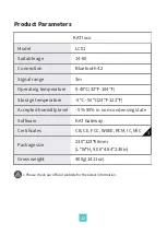
Page 12: ...C01 Connection Signal range Bluetooth 4 2 3m Accepted humidity level Operating temperature Storage temperature 0 40 32 104 5 50 23 122 Package size Software KAT Gateway 230 123 60mm L W H 9 06 4 84 2...

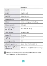
Page 13: ...Battery capacity Lithium ion polymer battery 370mAh Lighting LED Battery life 10hrs Housing material ABS 5V 0 5A 2A MAX Velcro Straps length 20cm 35cm 7 87in 13 78in Adjustable length for Velcro Stra...

Page 14: ...mm 0 94in Lithium ion Polymer Battery Charging voltage and current Charging time 1 hour Lighting LED Battery life 10hrs Housing material ABS 5V 0 5A 2A MAX Model Weight LC013 Receiver 80g 2 82oz Size...

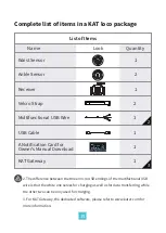
Page 15: ...g as well as for data transferring while the other two can be only used for charging 3 For KAT Gateway the dedicated software please refer to www katvr com for more information List of Items Name Wais...

Page 16: ...nt connection status of the device and run available VR content Thanks to its inSteam Turbo Mode each compatible game will be automatically launched with an optimal settings con guration You can also...

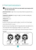
Page 17: ...sensors b Watch the status of the LED lights When it s charging there will be a diming light when it s fully charged there will be a long bright signal If lights out it s a signal of broken c Disconn...

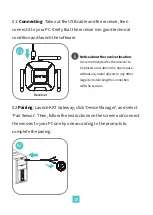
Page 18: ...plete the pairing Notice about the receiver location It is recommended for the receiver to be placed on a table in the open space without any metal objects or any other large items blocking the connec...

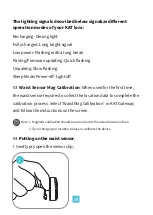
Page 19: ...Firmware updating Quick ashing Unpairing Slow ashing Sleep Mode Power o Light o 03 Waist Sensor Mag Calibration When used for the rst time the waist sensor requires to collect the location data to com...

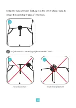
Page 20: ...the waist sensor in front right in the center of your waist to ensure the correct operation of the device II Skewed placement Upside down placement The pictures below show improper placement of the s...

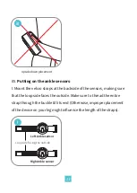
Page 21: ...sure that the loop side faces the outside Make sure to thread the entire strap through the buckle till its end Otherwise improper placement of the device on your leg might in uence the length of the s...

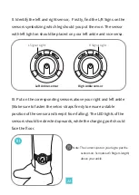
Page 22: ...nal Light Left Ankle sensor Righ Ankle sensor III Put on the corresponding sensors above your right and left ankle Make sure to fasten the velcro straps rmly to ensure a stable position of the sensor...

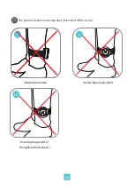
Page 23: ...23 Skewed placement Upside down placement The pictures below show improper placement of the sensor I II III Reversed placement of the right and left sensors...

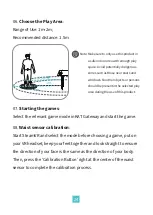
Page 24: ...ether and look straight to ensure the direction of your face is the same as the direction of your body Then press the Calibration Button right at the center of the waist sensor to complete the calibra...

Page 25: ...ctions such as stra ng can be made in Controller Options tab of KAT Gateway Note If the movement direction suddenly deviates rst check if the waist sensor is still placed at its starting position If n...

Page 26: ...26 I II Pull the waist sensor up gently to unclip it I Note Do not use excessive force to take o the sensors...

Page 27: ...iod please contact KAT VR or your local distributor Please present the product receipt to the place of purchase or another place designated by KAT VR KAT VR will decide whether to repair replace or re...

Page 28: ...Number Product Information Repair Records Warranty Period Service Date Check the terms and conditions of the warranty online DeviceIssue Product Condition ONE YEAR of free repair service Name Purchase...

Reviews: