background image

8.917-208.0  •  HOT •  Rev. 05/17

13


PRESSURE W

ASHER


OPERA

TOR’S MANU

AL
  

MAINTENANCE & SERVICE

Step 3  Attach a short section (3-5 ft.) of garden hose 

to machine to siphon solution from an elevated 
container. Turn machine on, allowing solution 
to be pumped through coils back into the con-
tainer. Solution should be allowed to circulate 
2-4 hours.

Step 4  After circulating solution flush entire system with 

fresh water. Reinstall high pressure nozzle into 
wand.

Rupture Disk

If pressure from pump or thermal expansion should 
exceed safe limits, the rupture disk will burst, allow-
ing high pressure to be discharged through hose 
to ground. When the disk ruptures it will need to be 
replaced. Torque the replacement rupture disk to 35 
foot pounds.

Fuel

Use clean fuel oil that is not contaminated with water 
and debris. Replace fuel filter and drain tank every 
100 hours of operation. Use No. 1 or No. 2 Heating 
Oil (ASTM D306) only. 

NEVER use gasoline in your 

burner tank. Gasoline is more combustible than fuel 
oil and could result in a serious explosion. 

NEVER 

use crankcase or waste oil in your burner. Fuel unit 
malfunction could result from contamination. 
Biodiesel fuels are becoming more popular as alter-
native fuels under the Green Initiative. Landa en-
dores the use of fuels that are blended with biodies-
els meeting ASTM D6751 and petroleum  
fuels meeting ASTM D396. Landa offers no  
opinion regarding the combustion characteristics  
of B5 blends. B5 biodiesel fuels are 5% ASTM 
D6751 biodiesel and 95% ASTM D396 fuel oil blend.
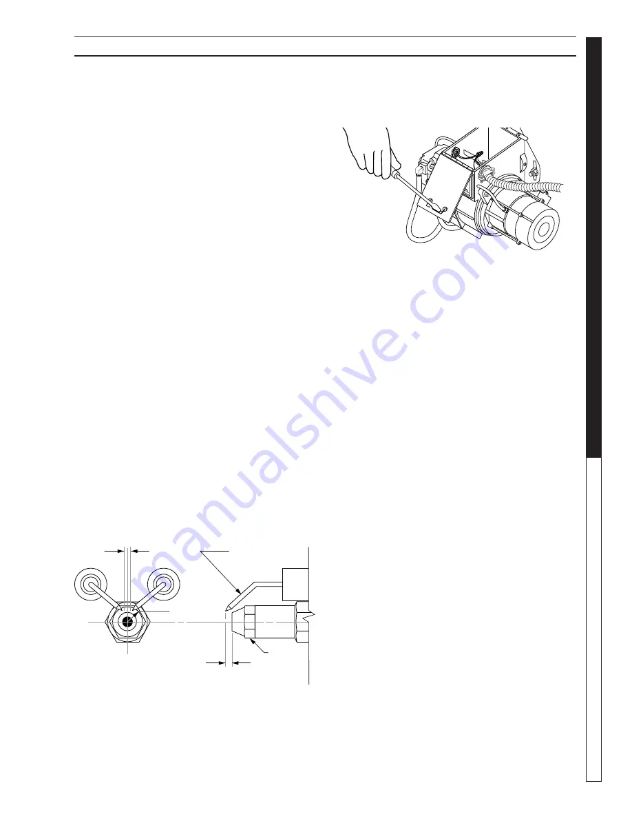
Electrode Setting

(See illustration below.)

Ignition Circuit

Periodically inspect wires, spring contact and elec-
trodes for condition, security and proper spacing. 
Transformer test: 

(CAUTION 10,000 VOLTS) use 

defect free insulated screwdriver and keep fingers  

Side View

Top View

1/16"

7/16"

5/32" Gap

Electrode

Nozzle

off blade! Lay blade across one contact: OK if arc  
will span 1/2" between end of blade and other  
contact (see illustration below).

Transformer Check

Burner Nozzle

Keep the tip free of surface deposits by wiping it with 
a clean, solvent-saturated cloth, being careful not to 
plug or enlarge the nozzle. For maximum efficiency, 
replace the nozzle each season.

Fuel Control System

These machines utilize a fuel solenoid valve located 
on the fuel pump to control the flow of fuel to the 
combustion chamber. This solenoid, which is nor-
mally closed, is activated by the unloader's pressure 
switch. When an operator releases the trigger on the 
spray gun, the unloader goes into a by-pass mode, 
thus stopping electrical current to the fuel solenoid 
coil. With the solenoid closed, the fuel supply to the 
combustion chamber ceases. Periodic inspection to 
insure that the fuel solenoid valve functions properly 
is recommended. This can be done by operating the 
machine and checking to see that when the spray 
gun is in the OFF position the burner is not firing.

Fuel Pressure Adjustment:

To adjust fuel pressure, turn the adjusting screw 
(located at the regulator port) clockwise to increase, 
counterclockwise to decrease. Do not exceed 200 psi.
NOTE: When changing fuel pump, a by-pass plug 

must be installed in return line port or fuel pump  
will not prime. 
To adjust fuel pressure, First install a pressure gage 
into the port just after the pump fuel exit. Turn the ad-
justing screw (located at the regulator port) clockwise 
to increase, and counterclockwise to decrease. Do 
not exceed 200 psi or lower the pressure below 130 
PSI, when checked at the post-pump pressure port.
The fuel pressure may need to be adjusted due to 
altitude. For every 500 ft altitude above sea level, the 
boiling point of water goes down 1 °F. At high altitude 
environments, this boiling point change may require 
the heat input to be lowered so the water input does 
not turn to steam earlier than at the factory settings 

Summary of Contents for Landa HOT 2-1100

Page 1: ...8 917 208 0 OPERATOR S MANUAL For technical assistance or the Landa Dealer nearest you consult our web page at www landa com HOT HOT 2 1100 HOT2 1500 HOT 4 2000 HOT 3 1100 HOT 3 300 89172080 1 ...

Page 2: ......

Page 3: ...ould record both serial number and date of purchase and keep in a safe place for future reference 8 917 208 0 HOT Rev 05 17 Introduction Important Safety Information 4 5 7 Component Identification 6 Installation 7 Assembly Instructions 8 Operating Instructions 9 Detergents General Cleaning Techniques 10 Shutting Down Clean up 11 Storage 11 Maintenance Service 12 14 Preventative Maintenance and Oil...

Page 4: ...a ground fault circuit interrupter GFCI If rated more than 250 volts or more than single phase this product should only be connected to a power supply receptacle protected by a GFCI DANGER Improper connection of the equipment grounding conductor can result in a risk of elec trocution Check with a qualified electrician or service personnel if you are in doubt as to whether the outlet is properly gr...

Page 5: ...bility of a fall due to slippery surfaces 20 Do not overreach or stand on unstable support Keep good footing and balance at all times 21 Do not operate this machine when fatigued or under the influence of alcohol prescription medications or drugs IMPORTANT SAFETY INFORMATION WARNING USE PROTECTIVE EYE WEAR AND CLOTHING WHEN OPERATING THIS EQUIPMENT WARNING High pressure spray can cause paint chips...

Page 6: ...tional 8 903 430 0 High Pressure Nozzle Detergent Pick up Tube Quick Coupler Power Supply GFCI Steam Nozzle Steam Wand 3 300 Spray Gun Trigger Variable Pressure Control Handle Variable Pressure Wand 2 11024D 2 15024D 3 11024D 4 2000 2 11026D 2 15026D Pump Switch High Pressure Hose Water Supply Hose not included Safety Latch Detergent Bucket not included Brass Soap Nozzle Brake Burner Switch Strain...

Page 7: ...ir may have to be piped to the burner and a fan installed bringing the air into the machine WARNING Avoid small areas or areas near exhaust fans Electrical The machine when installed must be electrically grounded in accordance to local codes Check for proper power supply using a volt meter The HOT 2 1100 HOT 2 1500 and HOT 3 1100 each require a 120V 20 amp receptacle to comply to the UL 1776 Stand...

Page 8: ...reads Move safety latch into locked position STEP 6 Check oil level by using supplied dip stick Use SAE 30W non detergent only STEP 7 Fill fuel tank with proper fuel 89172080 9 STEP 5 Release the coupler collar and push the nozzle until the collar clicks Pull the nozzle to make sure it is seated properly 89172080 3 89172080 4 Detergent Injector STEP 4 Pull the spring loaded collar of the wand coup...

Page 9: ...the vari able pressure control handle coun terclockwise to reduce pressure 89172080 13 Selection of high or low pressure is accompanied by turning the handle Note High pressure nozzle must be inserted at end of wand to obtain high pressure To apply soap read detergent instructions Variable Pressure Control Handle Trigger Variable Pressure Wand VP High Pressure Nozzle Brass Soap Nozzle 89172080 10 ...

Page 10: ...cleaning solu tion and apply to surface at low pressure for best results limit your work area to sections approxi mately 6 feet square and always apply detergent from bottom to top Allow detergent to remain on surface 1 3 minutes Do not allow detergent to dry on surface If surface appears to be drying simply wet down surface with fresh water If needed use brush to remove stubborn dirt Rinse at hig...

Page 11: ...tion This closes both the intake and exhaust valves to prevent rusting of cylinder 4 Cover the pressure washer and store in a clean dry place that is well ventilated away from open flame or sparks NOTE The use of a fuel additive such as STA BIL or an equivalent will minimize the formulation of fuel deposits during shortage Such additives may be added to the gasoline in the fuel tank of the engine ...

Page 12: ...nty Winterizing Procedure Damage due to freezing is not covered by warranty Adhere to the following cold weather procedures whenever the washer must be stored or operated outdoors under freezing conditions During winter months when temperatures drop below 32 F protecting your machine against freezing is necessary Store the machine in a heated room If this is not possible then mix a 50 50 solution ...

Page 13: ... 5 32 Gap Electrode Nozzle off blade Lay blade across one contact OK if arc will span 1 2 between end of blade and other contact see illustration below Transformer Check Burner Nozzle Keep the tip free of surface deposits by wiping it with a clean solvent saturated cloth being careful not to plug or enlarge the nozzle For maximum efficiency replace the nozzle each season Fuel Control System These ...

Page 14: ...r and the air band should be moved to allow the air to flow through the burner Sharp eye burning white fumes indicate too much air flow ing through the combustion chamber The air band should be moved to allow less air to flow through the burner To adjust Loosen locking screw found on the air band Start machine and turn burner ON and close air band until black smoke appears from burner exhaust vent...

Page 15: ...t enough to cause the flame tips to appear absolutely clean Removal of Soot and Heating Coil In the heating process fuel residue in the form of soot deposits may develop between the heating coil pipe and block air flow which will affect burner combustion When soot has been detected on visual observation the soot on the coil must be washed off Follow these steps to remove the coil 1 Disconnect hose...

Page 16: ...zzle Every 6 months Replace Quick Connects Annually Clean Water and Detergent Screen Filter Weekly Replace HP Hose If there is any sign of wear Grease Motor Every 10 000 hours Check Burner Nozzles Annually Unloader Valve Annually This pressure washer was produced with the best available materials and quality craftsmanship However you as the owner have certain responsibilities for the correct care ...

Page 17: ...e Insufficient water supplied Check water G P M to machine Restricted water flow Check nozzle for proper size or obstruc tion DETERGENT NOT DRAWING Air leak Tighten all clamps Check detergent lines for holes Valve in the injector head may be blocked dirty or damaged Clean or replace valve in injector Filter screen on detergent suction hose plugged Clean or replace Dried up detergent plugging meter...

Page 18: ...ter pressure Do not close trigger on spray gun for longer than 1 2 minutes OIL DRIPPINGS Oil seal worn Check and replace if necessary MACHINE SMOKES Improper fuel or water in fuel Drain tank and replace contaminated fuel Improper air adjustment Readjust air bands on burner assembly Low fuel pressure Adjust fuel pump pressure to specifications Weak fuel pump Check fuel pump pressure Replace pump if...

Page 19: ...achines with spray gun control for proper on off fuel flow control Clogged burner nozzle Replace Water not turned on Turn on water to activate burner flow switch Fuel solenoid malfunction Remove test for continuity and replace as needed Fuel solenoid malfunction Replace if needed Pressure switch malfunction Test for proper operation Replace if needed PUMP MOTOR STOPS AFTER A FEW MINUTES OF OPERATI...

Page 20: ...Form 8 917 208 0 Revised 05 17 Printed in U S A ...

Reviews: