715-721 • HDS-NG LP • 9.800-160.0 • Rev. 4/10
OPERATOR’S MANUAL
PRESSURE WASHER
20
MAINTENANCE & SERVICE
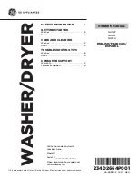
4. Replace manifold pressure adjustment screw
cap.
Figure 5
Pilot Burner Adjustment:
1. Remove pilot adjustment cap.
2. Adjust pilot key to provide properly sized flame.
3. Replace pilot adjustment cap.
Rupture Disk:
If pressure from pump or if thermal expansion should
exceed safe limits, the rupture disk will burst, allowing
high pressure to be discharged through hose to ground.
When the disk ruptures, it will need to be replaced.
Torque to 35 ft. lbs.
PROPANE GAS
(Vapor Fuel Only)
General Safety Precautions:
Have a qualified gas service person assist in any gas
burner installation or service. Few maintenance people
or mechanics are knowledgeable in gas controls or
related safety practices. Since propane gas is heavier
than air, unburned propane gas will gravitate to the floor
rather than rise out of the stack. Hence, adequate floor
space and good ventilation are especially important with
propane systems.
Gas Pressure Requirements:
All propane fired machines operate on gas phase
only. They are designed to operate at a pressure of 11
w.c.i. (between 1/3 and 1/2 of one PSI), and are often
operated at even higher pressures when extra heat is
needed.
Exterior regulators are needed to control the system.
Propane bottles are not included with the machine.
A high pressure regulator should be installed on the
propane bottle and a low pressure regulator attached
to the pressure washer.
Propane Cylinder Capacity:
An important consideration with propane systems is
the capacity of the supply cylinder relative to the needs
of the burner. The burner operates on propane as a
gas. As gas is used from the propane cylinder, the
liquid in the cylinder boils to maintain gas pressure.
This boiling process cools the liquid, and in a heavy,
continuous-demand situation, the liquid temperature
can fall to the point at which it cannot provide gas as
rapidly as is needed. In this case, it may be necessary
to warm the propane cylinder by directing a warm
spray, not over 120°, on the cold cylinder, or by mani-
folding two propane bottles together to increase total
vaporization capacity. It is recommended that a min-
imum 100 lb. propane bottle be used on the machine,
depending on the length of running time desired.
BURNER FEATURES
Operated Automatic Valve:
This machine is equipped with a thermopile self-pow-
ered combination gas control. This system is designed
as a constant burning pilot. Lighting of the pilot is ac-
complished by manually lighting the pilot. A thermostat
and flow switch control the main solenoid valve.
Care of Main Burner:
Because of condensation from the heater coils drip-
ping down on the burners, scale buildup may occur in
the burner jet orifices.
1. TO REMOVE BURNER MANIFOLD FROM
WATER HEATER COIL:
Turn off the gas at the main burner by turning the
knob to the “OFF” position on the gas valve and
main gas supply.
Disconnect the pilot and ignition lines from the
gas valve. Disconnect union in main burner line.
(Remove the nuts from the U-bolts, item 21 on
page 28). Slide burner manifold out through outer
wrap opening.
2. TO CLEAN BURNER JETS:
Select proper size drill for type of gas involved. Use
vise to hold drill and to ream out each jet orifice.
If the water heater will be exposed to freezing weather,
an antifreeze solution should be circulated through the
coils by whatever means are available for the particular
system the water heater is used on.
Gas Valve Adjustment
ON/OFF
Switch
Manifold Pressure
Adjustment Screw
Under Cap
Line to
Pilot
Light