background image

715-721 •  HDS-NG LP •  9.800-160.0  • Rev. 4/10
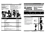
OPERATOR’S MANUAL


PRESSURE WASHER 


10

INSTALLATION

Venting:

This  machine  is  to  be  used  indoors  and  requires 
ventilation.
When venting the machine, if the machine is to be in 
an enclosed area with a vent pipe, be sure it is the 
same size as the stack on the machine. Poor draft will 
cause the machine to soot and not operate efficiently. 
When placing the machine for installation, position the 
vent pipe to be as straight as possible and to protrude 
through the roof of the building at a proper location and 
at sufficient height to eliminate down-draft. Venting of a 
gas fired machine shall be installed with a down-draft 
diverter located about 3 ft. above machine.
Input - BTU Per Hour 

Draft Hood & Flue Pipe 

Size


250,000 - 320,000 

8 inch


320,000 - 410,000 

9 inch


410,000 - 600,000 

10 inch


600,000 - 750,000 

12 inch

NOTE:  If  the  vent  pipe  exceeds  10  ft.  in  length,  or 
contains more than two elbows, use next size larger 
pipe and draft diverter or the burner will not ignite. No 
movable  vent  pipe  damper  should  be  used  on  any 
installation.

Draft Diverter:

Install the draft diverter above the heating coil. The 
diverter  enhances  the  draft  through  the  burner  by 
severing the chimney effect created in sections of vent 
pipe positioned below. It also helps prevent freezing 
of the coil due to wind chill factors.
Figure 3

When a room is of unusually tight construction and 
has  a  ventilating  fan,  which  may  be  used  for  ex-
hausting air outdoors -or has a vented exhaust — it 
is recommended that combustion air be supplied to 
the enclosed room through intakes extending to the 
outside of the building and terminating in down-turned 
fittings. These should be suitably arranged to prevent 
obstruction from snow or rain, and include a protecting 
screen not smaller than 1/4 inch mesh.
Figure 4


Illustration showing air openings necessary 

to supply air for combustion when installed  

in an enclosed room.

Water Source:

The water source for the machine should be supplied 
by a 5/8" I.D. garden hose with a city water pressure of 
not less than 30 PSI. If the water supply is inadequate, 
or if the garden hose is kinked, the machine will run 
very rough and the burner will not fire.

Water Connection:

Connect the high pressure hose by pulling the coupler 
collar  back  and  then  inserting  it  onto  the  discharge 
nipple. Secure it by pushing the collar forward.
Attach the wand into the spray gun using teflon tape 
on the pipe threads to avoid leaks.

Inspection and Testing Gas Piping:

The  building  structure  should  not  be  weakened  by 
installing  the  gas  piping.  The  piping  should  not  be 
supported by other piping, but should be firmly sup-
ported with gas hooks, straps, bands or hangers. Butt 
or lap welded pipe should not be run through or in an 
air duct or clothes chute.

Optional

When in a tightly closed room without ventilation open-
ings to the outdoors or other rooms, provisions shall be 
made for supplying air for combustion through special 
openings, one near the floor and the other near the 
ceiling, each to be sized on the basis of one square 
inch or more of free area for each 1,000 BTU input 
per hour (see Figure 4).

Ventilating Air Opening. 
1 square inch for each 
1000 BTU per hour input.

Summary of Contents for HDS NG 3.5/30 Ea St - 1.575-719.0

Page 1: ...S NG 5 0 30 Eb St 1 575 717 0 OPERATOR S MANUAL To locate your local K rcher Commercial Pressure Washer Dealer nearest you visit our web page at www karchercommercial com HDS NG 3 5 30 Ea St 1 575 719...

Page 2: ...Starting 11 Assembly Instructions 12 Operating Instructions 13 Detergents General Cleaning Techniques 14 Shut Down Cleanup 15 Storage 15 Basic Facts 16 Troubleshooting 17 18 Maintenance Service 19 20...

Page 3: ...250 volts or less single phase will be pro vided with a ground fault circuit interrupter GFCI If rated more than 250 volts or more than single phase this product should only be connected to a power su...

Page 4: ...specified in the manual 21 Do not replace LP tank while machine is running Serious injury could result WARNING Use vapor fuel only 22 The LP models are designed to run on vapor pro pane fuel Do not us...

Page 5: ...t from electrical source and shut off gas valve 26 Install this machine on non combustible flooring 27 Do not allow acids caustic or abrasive fluids to pass through the pump 28 Never run pump dry or l...

Page 6: ...siphon and mix detergents Wand Must be connected to the spray gun High Pressure Hose Connect one end to water pump discharge nipple and the other end to spray gun Note If trigger on spray gun is rele...

Page 7: ...715 721 HDS NG LP 9 800 160 0 Rev 4 10 7 PRESSURE WASHER OPERATOR S MANUAL INSTALLATION 9 57 I D 49 0 38 3 8 High Pressure Out 11 3 4 27 1 2 44 1 4 Gas In 1 1 2 NPT M 3 0 Fresh Water In 1 0 GHF 1 1 4...

Page 8: ...be piped to the burner and a fan installed to bring the air into the area 4 Do not locate near any combustible material Keep all flammable material at least 20 feet away Allow enough space for servici...

Page 9: ...low is based on gas pressure in the range 0 5 PSI specific gravity of 6 and pressure loss of 5 w c i Numbers are for straight schedule 40 pipe fittings further reduce capacity PROPANE Length of Pipe f...

Page 10: ...ommended that combustion air be supplied to the enclosed room through intakes extending to the outside of the building and terminating in down turned fittings These should be suitably arranged to prev...

Page 11: ...lighting the pilot follow these instructions exactly B BEFORE LIGHTING smell all around the appliance area for gas Be sure to smell next to the floor because some gas is heavier than air and will set...

Page 12: ...harge fitting STEP 4 Connect garden hose to the cold water source STEP 5 Check inlet filters re move debris then connect the garden hose to pump water inlet CAUTION Do not run the pump without water o...

Page 13: ...ote Thermostat should be set at 200 4 The pilot will ignite first then you will notice a flash of light indicating complete ignition Note You should hear a clicking sound before the pilot ignites STEP...

Page 14: ...ion and apply to surface at low pressure for best results limit your work area to sections approximately 6 feet square and always apply detergent from bottom to top Allow detergent to remain on surfac...

Page 15: ...and insert into one gallon of fresh clean water Pull trigger on spray gun and siphon water for one minute STEP 2 Turn push burner switch to OFF position Open spray gun allowing water to cool Then tur...

Page 16: ...C4H10 Vaporization Point F 43 7 31 1 Specific Gravity Vapor 1 522 2 006 Specific Gravity Liquid 0 508 0 584 Lbs per Gal Liquid 4 23 4 87 BTU per Cu Ft Vapor 2 563 3 39 BTU per Gal Liquid 91 547 102 0...

Page 17: ...valve repair replace Faulty flame sensor Test sensor wiring repair replace LOW OPERATING PRESSURE Faulty pressure gauge Install new gauge Insufficient water supply Use larger garden hose Clean filter...

Page 18: ...cations Restriction behind float tank screen removed Install restriction Hole in detergent line s Repair hole Strainer basket plugged Remove and clean Connections on selector valve loose Put teflon ta...

Page 19: ...man ner the pump is good and the unloader needs to be repaired or replaced If low pressure is still present then the pump needs repairing CAUTION When using this procedure to test com ponents keep the...

Page 20: ...s used from the propane cylinder the liquid in the cylinder boils to maintain gas pressure This boiling process cools the liquid and in a heavy continuous demand situation the liquid temperature can f...

Page 21: ...nance more often under severe conditions OIL CHANGE RECORD Date Oil Changed Month Day Year Estimated Operating Hours Since Last Oil Change MAINTENANCE SCHEDULE Replace Fuel Lines Annually Pump Oil Ins...

Page 22: ...VIEW 15 31 14 13 12 24 22 21 17 18 26 To Detergent Valve 80 35 36 73 36 34 37 38 33 32 25 See Burner Assy For Detail See Burner Assy For Detail 27 28 29 11 10 9 39 See Burner Assy For Detail 80 41 41...

Page 23: ...WASHER OPERATOR S MANUAL EXPLODED VIEW 55 For Detail See Float Tank Illus 66 52 56 52 68 67 54 48 50 49 47 67 46 51 57 11 10 65 For Detail See Electrical Illus 50 49 41 43 44 45 11 62 62 61 58 63 78...

Page 24: ...Label Incoming Power 1 21 9 802 041 0 Elbow 3 8 Steel 45 Street 1 22 8 707 185 0 Nipple 3 8 MPT x M22 Twist Coupler 1 23 9 800 152 0 Label RM 110 1 24 8 705 975 0 Nipple 1 2 Hex Steel 1 25 9 802 241...

Page 25: ...Bolt 3 8 x 1 NC HH 6 Model 719 0 9 64 9 803 130 0 Platform Motor 3 16 1 65 6 390 126 0 Clamp Hose 1 66 9 802 201 0 Clamp 6 w Motor 4 67 9 803 629 0 Clamp 16 3 68 9 802 985 0 Panel Left Side 1 69 9 803...

Page 26: ...PRESSURE WASHER 26 EXPLODED VIEW PARTS LIST ITEM PART NO DESCRIPTION QTY 90 9 800 023 0 Label 230V 3PH 717 0 1 9 800 024 0 Label 460V 3PH 721 0 1 9 800 025 0 Label 230V 1PH 715 0 719 0 1 91 9 196 012...

Page 27: ...n 28V 1 8 6 313 014 0 Spring Plate 1 9 5 321 377 0 Knob Main Switch 1 10 5 337 021 0 Plate Spring Metering Valve 1 11 5 321 379 0 Knob Metering Valve 1 12 9 803 609 0 Screw 4 x 12mm 4 13 9 803 635 0 P...

Page 28: ...G LP 9 800 160 0 Rev 4 10 OPERATOR S MANUAL PRESSURE WASHER 28 98001600 1 BURNER ASSEMBLY 19 28 5 4 14 15 23 27 13 9 10 10 11 9 12 5 7 38 37 38 8 3 5 5 6 1 2 16 17 7 18 31 29 22 20 30 33 21 34 24 35 3...

Page 29: ...4 9 803 132 0 Insulation Retainer Plate 1 15 9 802 798 0 Screw 10 x 1 2 TEK 4 16 9 802 975 0 Cover Burner Access 20 Coil 1 17 9 802 764 0 Screw 10 32 x 3 4 Hex Wash SL Mach Blk 2 18 9 800 028 0 Label...

Page 30: ...160 0 Rev 4 10 OPERATOR S MANUAL PRESSURE WASHER 30 3 1 5 9 8 11 14 18 3 12 13 15 17 Please See Specifications Pages 32 33 3 2 9 6 7 10 4 3 8 Please See Specifications Pages 32 33 ELECTRICAL BOX EXPLO...

Page 31: ...Nut 10 32 Keps 715 0 719 0 8 717 0 721 0 13 9 9 802 785 0 Nut 8 32 Keps 715 0 719 0 5 717 0 721 0 7 10 9 802 749 0 Screw 8 32 x 3 4 BHSOC CS 715 0 719 0 4 717 0 721 0 6 11 6 661 085 0 Capacitor 30 MF...

Page 32: ...Inhibitor 1 3 4 730 071 0 Filter Water Complete 1 4 5 063 226 0 Lid Scale Inhibitor 1 5 5 310 062 0 Nut Float Tank 1 6 5 443 285 0 Hose Stem 45 1 7 6 685 845 0 Valve Solenoid 1 8 6 362 078 0 O Ring 1...

Page 33: ...92 0 s Spare part set O rings 2 Swivel ends 3 standard 2 4 775 466 0 Easy Press Trigger Gun 22mm 1 3 4 760 550 0 Lance Spray Insulated 1050mm 1 4 Nozzles Please See Specifications Pages 5 3 401 210 0...

Page 34: ...or Block Pump Hertz Size Part Contactor Contact 1 575 715 0 3 530 644 0 6 5 220 1 06 1 2 883 402 0 8 724 283 0 8 724 361 0 1 575 717 0 3 530 646 0 9 6 220 3 06 1 2 883 402 0 8 724 280 0 8 724 361 0 1...

Page 35: ...condary Part Model Overload Fuse Fuse 715 0 8 724 306 0 6 661 085 0 6 661 181 0 9 803 662 0 2 Amp 9 803 663 0 5 Amp 9 803 664 0 717 0 8 724 305 0 NA 9 803 662 0 2 Amp 9 803 663 0 5 Amp 9 803 664 0 719...

Page 36: ...aded Pin M5x40 St 45H A2E ISO 4026 1 18 5 304 070 0 Hexagonal Head Screw 1 19 7 401 931 0 Sphere 5 K13 1 4401 Din 5401 1 ITEM PART NO DESCRIPTION QTY 20 5 582 121 0 Valve Disc 1 21 5 404 082 0 Hollow...

Page 37: ...589 0 Valve w Slot 1 44 5 443 474 0 Hose Stem 1 45 7 306 155 0 Cylinder Head Screw M12 x 100 8 8 A3E IS 4 47 5 110 853 0 Sleeve 2 49 6 362 547 0 O Ring Seal 20 0 x 1 5 NBR 70 2 50 7 306 043 0 Cylinder...

Page 38: ...er 3 8 5 332 289 0 Helical Spring 3 9 6 362 796 0 O Ring Seal 107 62 x 2 62 1 10 5 060 432 0 Housing 1 11 7 306 105 0 Screw M6 x30 8 8 R3R In6Rd 2 ITEM PART NO DESCRIPTION QTY 12 6 365 525 0 Grooved R...

Page 39: ...62 1 10 5 060 397 0 Housing 1 11 7 306 105 0 Screw M6 x 30 8 8 R3R In6Rd 2 12 6 365 059 0 Grooved Ring 22 x 30 x 6 8 3 13 5 115 520 0 Washer 3 14 6 365 056 0 Compact Seal 22 x 32 x 6 3 15 5 112 414 0...

Page 40: ...rew M8 x 20 8 8 A2E ISO 1 13 7 313 051 0 Spring Washer 8 FST A3E Din 7980 1 14 5 115 540 0 Washer 1 15 4 120 159 0 Swash Plate Complete 719 0 1 4 120 182 0 Swash Plate KPL 715 0 1 ITEM PART NO DESCRIP...

Page 41: ...0 1 11 5 411 100 0 Screw Plug 1 12 7 306 041 0 Cylinder Head Screw M8 x 20 8 8 A2E ISO 1 14 5 115 565 0 Washer 1 15 5 120 235 0 Swash Plate 1 ITEM PART NO DESCRIPTION QTY 16 6 401 225 0 Taper Roller...

Page 42: ...1 4 5 053 051 0 Bracket 1 5 6 631 807 0 Microswitch 1 6 7 314 664 0 Straight Grooved Pin 3 0 x 20 KU ISO 8740 1 All Models High pressur Electric motor HDS 4 0 20 4 2 0 Pump set 2 3 Switch High pressu...

Page 43: ...and lightning strikes 7 Defects caused by water sediments rust corrosion thermal expansion scale deposits or a contaminated water supply such as water in the unit with chloride content higher than tha...

Page 44: ...715 721 HDS NG LP 9 800 160 0 Revised 4 10 Printed in U S A...

Reviews: