9.800-103.0 • REV. 1/07
OPERA
TOR’S MANU
AL
PRESSURE
W
ASHER
12
MAINTENANCE
PREvENTATIvE
MAINTENANCE
1. Check to see that water pump is properly lubri-
cated.
2. Follow winterizing instructions to prevent freeze
damage to pump and coils.
3. Always neutralize and flush detergent from system
after use.
4. If water is known to have high mineral content, use
a water softener in your water system, or de-scale
as needed.
5. Do not allow acidic, caustic or abrasive fluids to be
pumped through system.
6. Always use high grade quality cleaning products.
7. Never run pump dry for extended periods of
time.
8. Use clean fuel: kerosene, No. 1 fuel oil, or diesel.
Clean or replace fuel filter every 100 hours of op-
eration. Avoid water contaminated fuel as it will
damage the fuel pump.
9. If machine is operated with smoky or eye burning
exhaust, coils will soot up, not letting water reach
maximum operating temperature.
1 0. Never allow water to be sprayed on or near engine
or burner assembly or any electrical component.
1 1. Periodically delime coils as per instructions.
1 2. Check to see that engine is properly lubricated.
It is advisable, periodically, to visually inspect the
burner. Check air inlet to make sure it is not clogged
or blocked. Wipe off any oil spills and keep equipment
clean and dry.
The flow of combustion and ventilating air to the burner
must not be blocked or obstructed in any manner.
The area around the pressure washer should be kept
clean and free of combustible materials, gasoline and
other flammable vapors and liquids.
MAINTENANCE AND SERvICE
Unloader valves:
Unloader valves are preset and tested at the factory
before shipping. Occasional adjustment of the unloader
may be necessary to maintain correct pressure.
Winterizing Procedure:
Damage due to freezing is not covered by warranty.
Adhere to the following cold weather procedures when-
ever the washer must be stored or operated outdoors
under freezing conditions.
During winter months, when temperatures drop below
32°F, protecting your machine against freezing is nec-
essary. Store the machine in a heated room. If this is
not possible then mix a 50/50 solution of anti-freeze
and water in the float tank. Turn the engine on to siphon
the anti-freeze mixture through the machine. If com-
pressed air is available, an air fitting can be screwed
into the float tank by removing the float tank strainer
and fitting. Then inject the compressed air. Water will
be blown out of the machine when the trigger on the
spray gun is opened.
High Limit Hot Water Thermostat:
For safety, each machine is equipped with a tempera-
ture sensitive high limit control switch. In the event that
the water should exceed its operating temperature,
the high limit control will turn the burner off until the
water cools then it will automatically reset itself. The
thermostat sensor is located on the discharge side of
the heating coil. The thermostat control dial is located
on the control panel.
Pumps:
Before running the pump check the pump crankcase for
a proper oil level. A proper oil level is indicated by the
red dot in the sightglass or between the high and low
marks on the dipstick. Use only SAE 30 non-detergent
oil. Change the initial oil after the first 50 hours and
then change the oil every 500 hours or every three
months.
When draining oil, clean inside of crankcase to remove
all impurities.
CAUTION:
When operating in damp
places or with high temperature fluctuations oil must
be changed immediately.
Cleaning of Coils:
In alkaline water areas, lime deposits can accumulate
rapidly inside the heating coil. This growth is increased
by the extreme heat build up in the coil. The best pre-
ventative for liming conditions is to use high quality
cleaning detergents. In areas where alkaline water is
an extreme problem, periodic use of Coil Conditioner
will remove lime and other deposits before coil be-
comes plugged. (See Deliming instructions for use of
Coil Conditioner.)
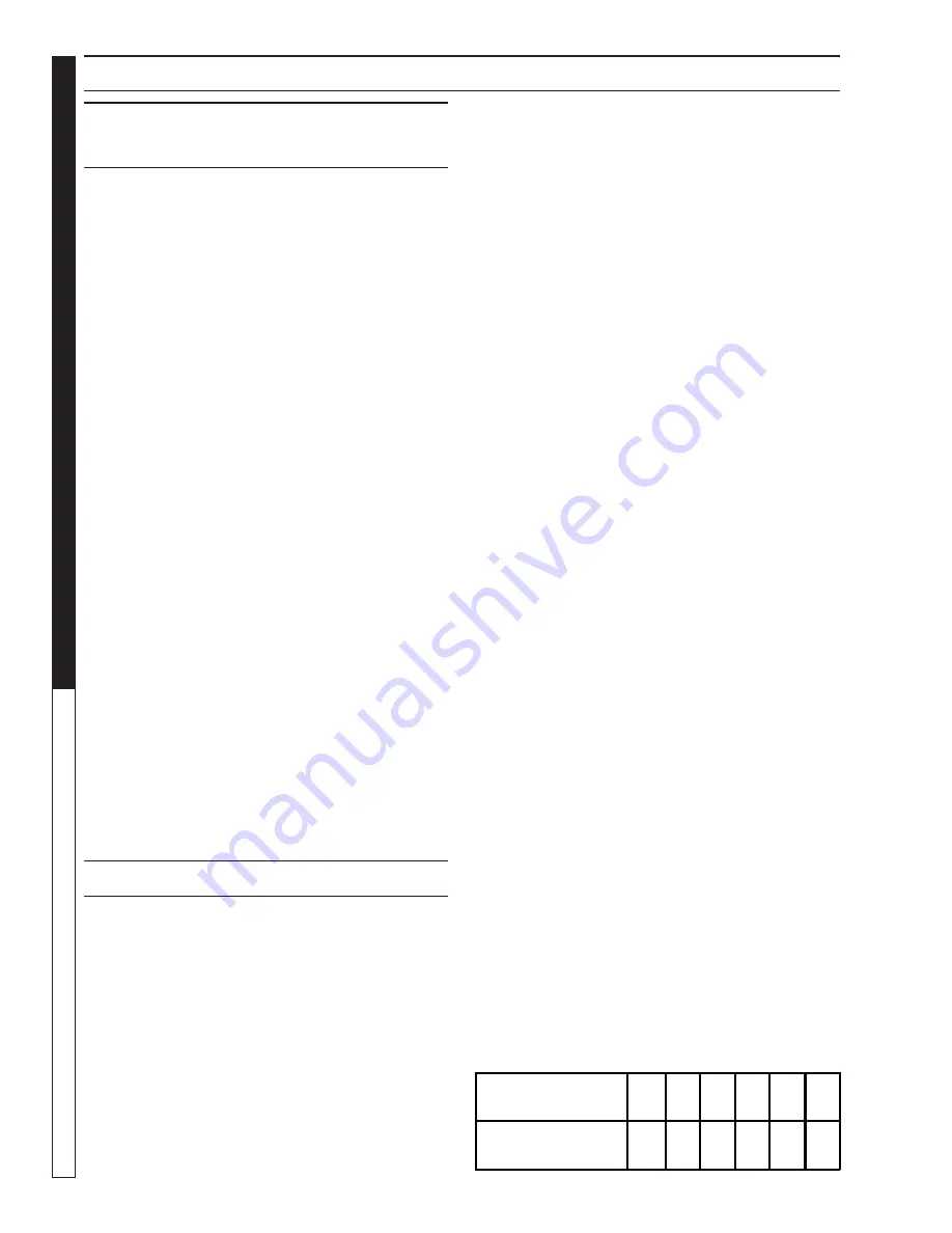
Scale Protection:
1. Fill container with Karcher scale inhibitor fluid
Rm 110.
2. Obtain water hardness values from local water
authority, or using a water hardness testing kit.
3. Adjust impulse transmitter in electric cabinet
(preset at #5.)
When operating unit without a scale protection,
the heater coil may become scaled.
Water hardness (
2
dH)
5
10
15
20
25
30
Impulse transmitter
10
8
7
6.5
6
5.5
Summary of Contents for HDS 4.0/32 Pe Cage
Page 2: ......
Page 44: ...Form 9 800 103 0 Revised 1 07 Printed in U S A...