background image

Operating Instructions

K&F SONA 8

KLING & FREITAG GMBH © 2016

Version 1.4

Page 3 of 21

Table of contents

1

Introduction

4

1.1

Icons  Used

4

1.2

About these operating instructions

4

2

Product Description

5

2.1

Items  Included

5

2.2

Components

5

2.3

Accessories

5

2.4

Required  Tools

5

3

Safety Instructions

5

3.1

Mounting the Speakers / Wall and Ceiling Installation

6

3.2

Notes for Mounting the Speakers

6

3.3

Preventing Hearing Damage

6

3.4

Protecting the Speakers / Operating Safety

7

4

Wall and Ceiling Installation

8

4.1

Temporary alignment of the speakers

8

4.2

Outlet for Cable and Safety elements

8

4.3

Wall Mounting of the Speaker

10

5

Stand Installation

11

6

Proper Alignment of the Loudspeakers

12

7

Wiring

12

7.1

Terminal assignment

12

7.2

Wiring  Diagrams

12

7.3

Wiring Instructions

12

8

Directions for the 100 volt connection.

14

9

First-time  Use

14

10

Technical Specifications

15

11

Measuring Diagrams

16

11.1

Coverage SONA 8

16

11.2

Frequency range SONA 8

16

12

Dimensions (with Mounting Arm)

17

13

Disposal

19

13.1

Germany

19

13.2

EU, Norway, Iceland, and Liechtenstein

19

13.3

All Other Countries

19

14

EC Declaration of Conformity

20

Summary of Contents for SONA 8

Page 1: ...ease Read Before Use KLING FREITAG GmbH Junkersstra e 14 D 30179 Hannover TEL 49 0 511 96 99 70 FAX 49 0 511 67 37 94 www kling freitag de Operating Instructions Translation of the original instructio...

Page 2: ......

Page 3: ...Safety 7 4 Wall and Ceiling Installation 8 4 1 Temporary alignment of the speakers 8 4 2 Outlet for Cable and Safety elements 8 4 3 Wall Mounting of the Speaker 10 5 Stand Installation 11 6 Proper Ali...

Page 4: ...p This icon marks information provided for simplified use of the described products 1 2 About these operating instructions KLING FREITAG GMBH All rights reserved All specifications regarding the featu...

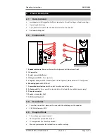
Page 5: ...ball joint 4 Hexagon nut M10 17 mm spanner 5 Long nut hexagon M10 black version 16 mm spanner white version 17 mm spanner 6 Mounting plate with M10 bolt 7 Connection terminal cover with outlet for cab...

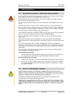
Page 6: ...before use If there are signs of wear cracks or deformation etc replace the affected parts immediately Visual inspection also includes checking all screwed connections of supporting components The inf...

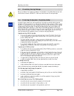
Page 7: ...ers Alternately you can also insert a clipping limiter before the amplifier To protect the loudspeaker from mechanical damage when high SPL is required a highpassfilter of 24 dB oct at 60 Hz has to be...

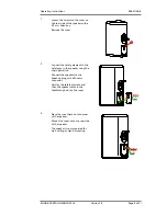
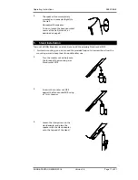
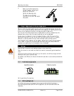
Page 8: ...the three hexagon socket srews only This way you can avoid having to tighten an hexagon socket screw that got covered by the Mounting Arm while you aligned the speaker Loosen this screw s just enough...

Page 9: ...e safety eye in the speaker using the chain quick link Connect the speaker via the Speakon plug or the Phoenix connector First lay the safety element and then the speaker cable in the feedthrough slot...

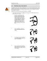
Page 10: ...mounting plate you can also mount the Mounting Arm with other suitable 10 mm bolts Screw the mounting plate onto the wall or ceiling using all four mounting holes Choose fasteners that are suitable fo...

Page 11: ...ount a SONA 8 speaker on a stand you need the accessory Stand socket M10 1 For stand mounting you do not need the provided long nuts Unscrew them from the mounting arm and keep them for possible later...

Page 12: ...anding systems result in a greater difference in volume between front and back seats than higher standing systems To simulate the correct alignment of the speakers beforehand there are various program...

Page 13: ...e speakers at the amplifier is correct When simultaneously using power amplifiers from different manufacturers be sure to use the correct specific pin configuration It may be necessary to modify the p...

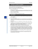
Page 14: ...system If there is interference turn off all appliances in the reverse order and check all cable connections Successively turn up the individual power amplifier channels and send a signal with low vo...

Page 15: ...al IEC 268 5 500 W program 1000 W Peak SPL 1 W 1 m 93 dB SPL Max SPL 1 m 124 dB SPL Components 8 low mid chassis 1 Hochtontreiber mit 45 mm Titanmembran CD Horn Impedance nominal 8 Ohm connectors behi...

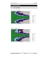
Page 16: ...Operating Instructions K F SONA 8 KLING FREITAG GMBH 2016 Version 1 4 Page 16 of 21 11 Measuring Diagrams 11 1 Coverage SONA 8...

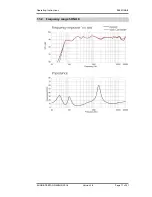
Page 17: ...Operating Instructions K F SONA 8 KLING FREITAG GMBH 2016 Version 1 4 Page 17 of 21 11 2 Frequency range SONA 8...

Page 18: ...12 Dimensions with Mounting Arm 250 6 mm 9 866 inch 120 mm 4 724 inch 461 6 mm 18 175 inch 29 440 6 mm 17 346 inch 285 3 mm 11 233 inch 102 1 mm 4 018 inch 140 mm 5 512 inch 5 mm 0 197 inch 450 5 mm...

Page 19: ...ossed out garbage can with a white bar below it The icon indicates that the equipment was distributed on or after 24 March 2006 and must not be disposed of through household waste KLING FREITAG GmbH i...

Page 20: ...SONA 6 SONA 8 SONA SUB SONS SUB II SW 112 SW 115D SW 115E SW 118E SW 212E These products are discontinued These systems are not covered by the Low Voltage Directive because of the rated voltage used W...

Page 21: ...Operating Instructions K F SONA 8 KLING FREITAG GMBH 2016 Version 1 4 Page 21 of 21 Managing Director CEO...

Reviews: