


SSV WORKS, 201 N. Rice Ave Unit A, Oxnard, CA 93030
www.SSVworks.com | Phone: 818-991-1778 | Fax: 866-293-6751
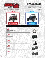
RZ34-Q5XARC
RZR 3 and RZR 4 with Ride Command
SSV Works 5 Speaker Audio Kit
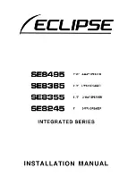
Phase 5
Panels, Dash Disassembly,
and Wiring
Glovebox Subwoofer
Installation
Amp Tray
Installation
pg
6
pg
10
pg
14
Cage Mount Speakers
Installation
pg
17
Kick Panel Speakers
Installation
pg
15
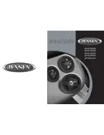
RZR3
2014-2018
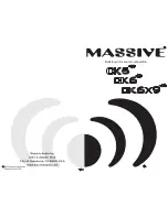
RZR4
2019+
RED
BLUE
FOLLOW THE COLOR CODE ON EACH STEP FOR YOUR VEHICLE’S SPECIFIC INSTRUCTIONS