background image

21

Kamstrup A/S • 55121739_B1_GB_02.2020

MULTICAL® 403

10  Set-up via front keys

It is possible to set up a number of parameters in MULTICAL® 403 at the installation site. The 
setup is carried out via the SETUP loop that is available as long as MULTICAL® 403 is in transport 
state*, or until you finish the setup with ”EndSetup”. If the meter has been put into operation and 
is thus no longer in transport state, it is necessary to break the meter’s installation seal to be able 
to access the SETUP loop again. This is done by separating and immediately after reassembling 
the top and base of the calculator. Thereafter, the meter must be sealed with sealing wire and/or 
sealing label to be used for billing purposes.
You go from USER loop to SETUP loop by pressing the left key (primary key) for 9 s. After 4 min. 
without activation of the front keys the meter returns to energy reading in USER loop.
SETUP loop does not include secondary readings, and, therefore, the index number always 
consists of 4 digits. In SETUP loop the right key (secondary key) is used for accessing individual 
readings with the purpose of changing parameters.

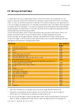
*****

SETUP loop

Index number in 
display

1.0

Customer number (N

o

 1)

3-001

2.0

Customer number (N

o

 2)

3-002

3.0

Date

3-003

4.0

Time**

3-004

5.0

Yearly target date 1 (mm.DD)

3-005

6.0

Monthly target date 1 (DD)

3-006

7.0

Flow sensor position: inlet or outlet flow (A-code)

3-007

8.0

Measuring unit and resolution 
(B and CCC-codes are configured as e.g. ”0.001 MWh” and ”0.01 m

3

”)

3-008

9.0

Primary Address Module (N

o

 35)

3-009

10.0 Average time for min./ max. P and Q

3-010

11.0

q

hc

***

3-011

12.0 t offset

3-012

13.0 Radio ”ON” or ”OFF”

3-013

14.0 Input A (pre-set register)

3-014

15.0 Input B (pre-set register)

3-015

16.0 Meter no. of Input A

3-016

17.0 Meter no. of Input B

3-017

18.0 TL2

3-018

19.0 TL3

3-019

20.0 TL4

3-020

21.0 t5

3-021

22.0 EndSetup

3-022

*  MULTICAL® 403 remains in transport state until flow is registered for the first time.
**  The clock can be adjusted under installation seal via the front keys or the PC-program 

METERTOOL HCW. Furthermore, all modules can adjust the clock.

*** 

q

hc

 can only be changed in meters configured as meter type 6. Upon attempts to access this 

menu in meters configured with other country codes the display shows the message ”Off”.

Summary of Contents for MULTICAL 403

Page 1: ...Installation and user s guide MULTICAL 403 Kamstrup A S Industrivej 28 Stilling DK 8660 Skanderborg T 45 89 93 10 00 info kamstrup com kamstrup com...

Page 2: ...es must be drawn at min 25 cm distance from other installations Climatic environment Non condensing closed location installation indoors ambient temperature 5 55 C Maintenance and repair The district...

Page 3: ...supply 14 7 Testing of function 15 8 Electrical connection 15 9 Communication modules 16 9 1 Module overview 16 9 2 Pulse inputs 16 9 3 Pulse outputs 17 9 4 Data Pulse inputs In A In B type HC 003 10...

Page 4: ...s must be obeyed Pressure stage PN16 PN25 see marking Pressure stage Kamstrup sensor pair type DS PN25 Pressure stage Kamstrup pocket sensors type PL PN25 At medium temperatures above 90 C we recommen...

Page 5: ...either be exposed to jerking nor pulling Please be aware of this when binding the cables and be careful not to pull the binders unnecessarily tight as this may damage the cables Please also note that...

Page 6: ...pocket and secure the cable by means of the enclosed M4 sealing screw Fasten the screw with your fingers only Seal the pockets using seal and locking wire SECTION B B SCALE 1 1 B B SECTION B B SCALE 1...

Page 7: ...either PN16 or PN25 see marking Any provided blind plug extension and gland can be used with both PN16 and PN25 In connection with flow sensors with the nominal dimensions G Bx110 mm and G1Bx110 mm i...

Page 8: ...to be placed immediately before or after a pump G Ought not to be placed immediately after a double bend in two planes A B C D E F G In order to avoid cavitation the back pressure at the flow sensor t...

Page 9: ...3 2 Flange meters and screw type meters 3 5 m3 h 1 2 2 45 0 45 0 45 45 The flow sensor can be mounted at an angle of 0 and may be turned 45 upwards or 90 downwards Note In installations where the med...

Page 10: ...om the left Flow from the right Flange meter Flow from the left Flow from the right 3 5 Humidity and condensation If there is risk of condensation e g in cooling systems a condensation proof MULTICAL...

Page 11: ...s used The construction of MULTICAL 403 always provides minimum installation depth in connection with compact mounting Due to the design the mounting radius in critical places remains 60 mm both at 45...

Page 12: ...S 55121739_B1_GB_02 2020 MULTICAL 403 4 3 Position of calculator If the flow sensor is installed in a humid or condensing environment the calculator must be wall mounted and positioned higher than th...

Page 13: ...ach functionality has its own digit dedicated to the indication of relevant information For instance all information concerning temperature sensor t1 is shown in the display as the second digit from t...

Page 14: ...ction class II and are connected via two wire cable without earth through the big cable bush the second one from the right at the bottom of the connection base Use connecting cable with an outer diame...

Page 15: ...nd check that the displayed values for temperatures and water flow are credible values 8 Electrical connection The two matched two wire sensors are mounted in terminals 5 and 6 t1 as well as 7 and 8 t...

Page 16: ...A HC 003 43 PQT Controller HC 003 50 Low Power Radio inputs In A In B 434 MHz HC 003 51 Low Power Radio GDPR inputs In A In B 434 MHz HC 003 66 BACnet MS TP inputs In A In B HC 003 67 Modbus RTU input...

Page 17: ...uts always follow the least significant digit displayed for energy and volume respectively 9 4 Data Pulse inputs In A In B type HC 003 10 The data terminals are for example used for connecting a PC Th...

Page 18: ...us module has been designed to be part of Kamstrup s hand held Wireless M Bus Reader system which operates within the unlicensed frequency band in the 868 MHz area The radio module is available with e...

Page 19: ...motor valve can be made by short circuiting the test points Up or Dn The module requires that the meter is mains supplied The module requires an external power supply 9 12 Low Power Radio inputs In A...

Page 20: ...ables are connected to the terminals 137 138 and 139 The module requires that the meter is mains supplied 9 15 Modbus RTU inputs In A In B type HC 003 67 Modbus is often used in building automation sy...

Page 21: ...secondary key is used for accessing individual readings with the purpose of changing parameters SETUP loop Index number in display 1 0 Customer number No 1 3 001 2 0 Customer number No 2 3 002 3 0 Dat...

Page 22: ...22 Kamstrup A S 55121739_B1_GB_02 2020 MULTICAL 403...

Page 23: ...gs Consumed energy in kWh MWh or GJ Activate to view yearly and monthly log values Volume of water consumed Activate to view yearly and monthly log values Number of operating hours Activate to view er...

Page 24: ...Kamstrup A S 55121739_B1_GB_02 2020 User Guide MULTICAL 403 Kamstrup A S Industrivej 28 Stilling DK 8660 Skanderborg T 45 89 93 10 00 info kamstrup com kamstrup com...

Reviews: