background image

34

Kamstrup A/S • 5512853_C1_GB_01.2017

M-Bus Master MultiPort 250D

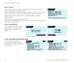
This screen may appear if an attempt is made to read an energy meter that does 
not support M-Bus logs.

In this case, arrows in the bottom left and bottom right indicate that more logged 
items are ready to be displayed using the left ( ) and right arrow buttons ( ). 

A logged value showing the 
timestamp and the associated value 
shown in two succesive displays

The last entry in the log, only the left arrow is displayed.

7.8  Settings of MultiPort 250D

A number of configurations can be set via the master’s display.
All settings will be remembered, even if the master is without supply voltage.
Press   to save the settings.

Summary of Contents for M-Bus Master MultiPort 250D

Page 1: ...M Bus Master MultiPort 250D Installation and User Guide Kamstrup A S Industrivej 28 Stilling DK 8660 Skanderborg T 45 89 93 10 00 info kamstrup com kamstrup com ...

Page 2: ...f M Bus Master MultiPort 250D 18 4 2 Electrical conditions in an M Bus network 18 4 2 1 M Bus modules 18 4 3 Installation parameters 18 4 3 1 Cable 19 4 3 2 Cable topology 20 4 3 3 Examples of network sizes 23 5 M Bus addressing 24 5 1 Primary addressing 24 5 2 Secondary addressing 24 5 3 Enhanced secondary addressing 24 6 M Bus communication 25 6 1 Communication speed 25 6 2 Transparent reading 2...

Page 3: ... 8 Settings of MultiPort 250D 34 7 8 1 Date and time 35 7 8 2 Contrast 35 7 8 3 M Bus 35 7 9 Green Mode 37 7 10 Other settings 37 7 11 PIN code 38 7 12 Advanced 38 7 12 1 Reading a specific meter via the M Bus address 39 7 12 2 Reading a meter via secondary address 39 7 12 3 View last Meter Reading 39 7 12 4 Network Troubleshooting 40 7 12 5 Information loggers 40 7 12 6 Factory settings 41 7 12 7...

Page 4: ...upled in cascade and only secondary addressing is used a total of 1 250 meters can be connected and the total cable length can be up to approx 14 km If primary addressing is used up to 250 meters can be connected Communication in the M Bus network is asynchronous serial bit transmission in half duplex which means that it is only possible to communicate in one direction at a time Communication spee...

Page 5: ...hich makes it simple to perform scanning reading and analysis of the M Bus network Furthermore the display currently provides information on network status such as current communication and number of connected meters Unit Loads Configured as a level converter one or several of the integrated communication ports are connected to a reading system a control unit or similar Communication is controlled...

Page 6: ...5 24 25 24 25 24 25 24 25 24 25 24 25 53 54 24 25 53 54 The master s module area provides extra communication options e g GSM GPRS and also prepares the master for additional future functionalities The integrated web server enables remote operation of the master as to configuration scanning and reading via RS 232 RS 485 and USB Operation via keys and communication through the optical eye can be pr...

Page 7: ... total of 1250 meters Up to 14 km cable length 300 2400 and 9600 baud communication speed Byte recovery Echo suppression Transient protection Integrated USB RS 232 RS 485 and optical eye with automatic port controller Module area for e g GSM GPRS module All ports are transparent and galvanically separated from the M Bus network Integrated web server for remote configuration analysis and reading PI...

Page 8: ...ection class of M Bus Master MultiPort 250D can be up to IP 67 IP 67 means full dust protection as well as water tightness for minimum 30 minutes down to 1 metre In order to obtain the highest IP protection the cables used must be correctly mounted through the master s unions USB RS 485 RS 232 4 sets of M Bus outputs M Bus input for cascade mode Mains 100 230 V 50 60 Hz ...

Page 9: ...ble length 15 m 105 RxD 2 Received Data 106 TxD 3 Transmitted Data 107 GND 5 Ground 108 DTR 4 Data Terminal Ready 109 CTS 8 Clear To Send 111 DSR 6 Data Set Ready 112 RTS 7 Request To Send RS 485 Max recommended cable length 1 200 m 137 A Transmit Receive inverted 138 A Transmit Receive non inverted 139 GND Ground M Bus Repeater Input Jumper must be set to Repeater 53 L1 M Bus input to master in r...

Page 10: ...for M Bus communication on an equal basis with the other serial connections The following communication speeds can be used for M Bus communication 300 baud 8E1 2400 baud 8E1 9600 baud 8E1 USB version 2 0 which allows up to 5 m cable length is used In connection with other USB versions than 2 0 the maximum cable length recommended is 3 m The master s integrated port controller makes sure that commu...

Page 11: ...e M bus Master area clik on Go to download and you will see this page Click the Download USB driver link You will now be asked to select Run or Save When selecting Run the installation starts automatically When the program is retrieved it is saved under C Kamstrup M Bus Master 250D When selecting Save the popup bar changes to Click Run or Open folder to run KamstrupMBusUSB exe ...

Page 12: ...12 Kamstrup A S 5512853_C1_GB_01 2017 M Bus Master MultiPort 250D When the setup program has been started just follow the instructions in the wizard Click Next to continue or Cancel to stop the setup ...

Page 13: ...512853_C1_GB_01 2017 M Bus Master MultiPort 250D The Device Driver Installation wizard starts to run Depending on the security settings in your computer this popup may occur Pressing Finish the installation is completed ...

Page 14: ...he following communication speeds can be used for M Bus communication 300 baud 8E1 2400 baud 8E1 9600 baud 8E1 Maximum recommended cable length is 15 m The master s integrated port controller makes sure that communication is only possible on one serial port at a time The master is available with a factory mounted 145 cm RS 232 cable fitted with a DB9F female connector 1 2 3 4 5 6 7 8 9 RS 232 conn...

Page 15: ...M Bus communication on an equal basis with the other serial connections The following communication speeds can be used for M Bus communication 300 baud 8E1 2400 baud 8E1 9600 baud 8E1 The master s integrated port controller makes sure that communication is only possible on one serial port at a time 3 7 M Bus Output All meters in an M Bus network are connected to M Bus output terminals 24 and 25 Th...

Page 16: ...otal cable length If one master and four repeaters are installed in a network the total cable length can be extended to approx 14 km and up to 1250 meters can be connected The master is configured as repeater by placing the jumper on the connector marked Repeater Using an M Bus Master MultiPort 250D as a repeater the M Bus network in front of the repeater is connected to M Bus Repeater In on termi...

Page 17: ... used The cabling topology is typically star or bus or a combination of both The connection in M Bus is independent of polarity and no termination resistance at the end of the cabling is needed If a cable type with shield is used it is important that the two M Bus conductors are not connected to ground or shield No precise indication as to maximum cable length in an M Bus network can be given as i...

Page 18: ...is a high degree of certainty that all meters can be read If the voltage is between 20 and 24 V it will probably be possible to read all meters If the voltage is between 18 and 20 V the meter may be read If the voltage is below 18 V it is most likely that the meter cannot be read There must be no communication on the M Bus network when the above measurement is made 4 2 1 M Bus modules Each M Bus m...

Page 19: ...33 53 19 0 8 0 50 35 29 1 0 0 79 23 45 1 13 1 00 18 57 1 26 1 25 14 71 1 39 1 52 12 87 1 6 2 0 8 7 115 Examples of resistance in copper cable Please note that the resistance in copper depends on its purity The purer the copper the lower its resistance LiYY 2x0 34 mm2 2x0 50 mm2 2x0 75 mm2 2x1 0 mm2 2x1 5 mm2 Current load Max 4 5 A Max 6 A Max 10 A Max 12 A Max 18 A Cable resistance 56 Ω km 39 Ω km...

Page 20: ...tion of both The advantage of bus topology is shorter wires The disadvantage is that a cable interrupt will mean that all the following meters can no longer be read The advantage of star topology is the fact that all the other meters can still be read after a cable interrupt The disadvantage is a large consumption of cable with a high leading load which reduces the maximum cable length and makes a...

Page 21: ...02 602 602 602 M Bus Master Bus topology with cable looped through meters 602 602 602 602 602 M Bus Master Bus topology with each individual meter connected to the bus 602 602 602 602 M Bus Master Star topology connecting each individual meter directly to the M Bus Master ...

Page 22: ...602 602 602 602 602 602 602 M Bus Master M Bus Master 602 602 602 602 M Bus Master M Bus Repeater 24 25 24 25 53 54 24 25 1st floor 2nd floor 3rd floor 4th floor Area 1 Area 2 Area 4 Area 3 Junction box Example of the construction of a large M Bus network Dividing the connected meters into several separate cable networks and connecting those individually to the master will simplify troubleshooting...

Page 23: ... Number of meters 10 50 150 250 300 baud 10 000 m 3 500 m 1 200 m 700 m 2400 baud 7 000 m 3 500 m 1 200 m 700 m 9600 baud 3 500 m 3 500 m 1 200 m 700 m Possible cable lengths with meters evenly distributed in the cable network Cable type 1 5 mm2 12 Ohm 110 nF Speed Number of meters 10 50 150 250 300 baud 10 000 m 8 000 m 2 800 m 1 600 m 2400 baud 10 000 m 8 000 m 2 800 m 1 600 m 9600 baud 3 500 m ...

Page 24: ...ess between 001 and 250 If more than one meter have the same address a collision will occur and the meters cannot be read Kamstrup M Bus modules automatically use the last 2 3 digits of the customer number as their primary addresses 5 2 Secondary addressing 00000001 99999999 Secondary addressing uses the last 8 digits of the meter number as M Bus ID Kamstrup MULTICAL meters use the customer number...

Page 25: ...cation speeds 300 baud 8E1 2400 baud 8E1 9600 baud 8E1 not via GPRS 6 2 Transparent reading MultiPort 250D is equipped with the following communication possibilities for reading from e g remote reading systems control systems and various controllers with M Bus interface USB RS 232 RS 485 Optical eye GSM GPRS optional equipment Communication through the above mentioned ports is transparent and incl...

Page 26: ...when viewing a list shortcut when shortcut corner is shown or go right when e g entering a value or setting date and time Down Moves in the display downwards in the menu Up Moves in the display upwards in the menu Back Goes one level back upwards in the menu or back to the previous screen if a shortcut key has been used OK Starts the function which has been selected with the arrows keys or saves a...

Page 27: ...ata being sent 7 2 4 Overload Red light emitting diode which flashes when the load on the M Bus network is between 375 and 500 mA It is permanently lit when the load on the M Bus network exceeds 500 mA 375 mA corresponds to 250 UL M Bus Unit Loads At 500 mA M Bus Master MultiPort 250D disconnects due to overload or short circuit condition 7 3 Display The resolution of the backlit display is 128x64...

Page 28: ...nd date the configuration of the master as master or repeater and the number of unit loads with which the meters load the master Typically the load of one meter is 1 unit load If PIN code protection is on a padlock is displayed The main menu shows the different menus available in the master Status menu Main menu 7 5 Meter search by means of MultiPort 250D Carrying out a meter search scanning by me...

Page 29: ...imary scanning scans for meters with M Bus addresses between 001 and 250 Select type of scanning Select speed Primary scanning Scanning completed When performing an additional scanning it is possible to keep the existing scanning list and add additionally found meters to the list Re scanning ...

Page 30: ...s of the meter number being replaced by F Select type of scanning Select speed Note During a secondary scanning the Overload LED may flash if more than 20 meters reply to the master at the same time This is quite normal during a secondary scanning Secondary scanning Scanning completed When performing an additional scanning it is possible to keep the existing scanning list and add additionally foun...

Page 31: ...nning with prim addr When the meter has been read the first data appears in the display which also indicates the total number of registers that can be read The example to the left displays registers 1 to 5 of a total of 50 registers Scroll using and When pressing again reading data is displayed in detailed resolution The meter is being read The meter has been read When reading MULTICAL meters both...

Page 32: ... is to be read You just select the meter to be read from the menu Read Meter and press Main menu Meter reading 7 7 Reading M Bus loggers by means of MultiPort 250D The MULTICAL 403 contains several loggers readable by the M Bus Master 7 7 1 Read Logger From the Main Menu select Read Logger and press Select the logger periods to read Year Month Daily Minute 1 or Minute 2 and press The minute logger...

Page 33: ...t to read the log and press The M Bus master starts reading the logs from the selected energy meter During reading a progress bar is shown until data is ready 7 7 2 Display of logged data Reading of log is completed The index in the top right corner indicactes in this example that the first entry of 5 logs is shown The arrow in the bottom right indicates that more data is ready to be displayed by ...

Page 34: ...at more logged items are ready to be displayed using the left and right arrow buttons A logged value showing the timestamp and the associated value shown in two succesive displays The last entry in the log only the left arrow is displayed 7 8 Settings of MultiPort 250D A number of configurations can be set via the master s display All settings will be remembered even if the master is without suppl...

Page 35: ...ast of the display can be adjusted for optimum reading 7 8 3 M Bus NKE Delay NKE Delay sets the master s delay after having sent a normalisation initialisation to the meters in the network An initialisation has the effect that all modules are reset and collect new data from the meters Some module types require initialisation in order to be read Other module types need a period of time after initia...

Page 36: ... the master the scanning speed can be set to Fast which improves the scanning speed during meter search Timing Delay Baud Change Delay Baud Change Delay sets how long the master must pause scanning when switching to another baud rate in the menu Scan All Baud Baud Change Delay is per default 700 ms Bus Collision Delay Bus Collision Delay sets how long the master must pause before continuing scanni...

Page 37: ...nication ports as well as when a front button is pressed If Green Mode is used in conjunction with a reading program the program should be configured to send an initialisation SND_NKE followed by a pause of one minute before reading is started with the M Bus reading command REQ_UD Green Mode Bus Off Delay sets the time the master waits to switch off the M Bus power after last detected communicatio...

Page 38: ...protected by a PIN code The value is changed using and and the left and right function keys are used for switching between the individual digits Press in order to activate the PIN code A padlock is displayed when the PIN code function is active If the padlock is open the master is unlocked the padlock is closed when the master is locked The master is automatically locked approx 30 minutes after en...

Page 39: ... rate addressing form and M Bus address via the function and arrow keys 7 12 2 Reading a meter via secondary address Instead of scanning the whole network in order to read a single meter the meter can be read by selecting its M Bus address Address and baud rate are selected using the function and arrow keys 7 12 3 View Last Meter Reading Data of the latest meter reading can be displayed by the mas...

Page 40: ...e meters mounted before the master Communication from the master can be effected using keys and display as well as RS 232 USB and optical eye When the troubleshooting has been finished the operator must reconfigure to repeater using the keys or restarting the master Change to master Change to repeater 7 12 5 Information loggers The M Bus master has two loggers with information on previous events M...

Page 41: ...tory settings The master s settings can be restored to the default values it had when it was produced Please note that loggers are reset too 7 12 7 Communication Test Communication test is used for testing communication between the master and a meter The test can be used with either primary or secondary addressing and one more or all baud rates Setting is done via the function and arrow keys ...

Page 42: ...Noise bytes show the number of bytes received without any ongoing communication Performed scanning will be counted as noise Bus Restarts show how many times the master has restarted due to overload and short circuit conditions 7 12 9 Restart master If it is not possible to switch off the power supply the master can be restarted by selecting the menu Reboot Select Reboot Device 7 12 10 About M Bus ...

Page 43: ... MultiPort 250D 8 Web Server Please see Installation and User Guide no 55121707 http products kamstrup com AMR AMI AMM Smart Grid AMR and AMI Devices M Bus Networks Masters M Bus Master max 250 meters connected Installation and User Guide GB Web Server ...

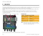
Page 44: ... and the M Bus Master is established by means of a jumper The external antenna must be connected as shown below and placed well away from the M Bus master and the connected network wires Antenna connection Jumper Connection of supply SMS command SIGNAL for reading the signal strength Syntax command SIGNAL Syntax return answer Signal signal strength 0 31 Example SIGNAL Return answer correct Signal ...

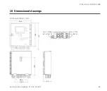
Page 45: ...45 Kamstrup A S 5512853_C1_GB_01 2017 M Bus Master MultiPort 250D 10 Dimensioned drawings All measurements in mm 168 184 210 3 pcs M16 ø4 8 mm 6 pcs M12 ø3 6 mm 80 5 140 5 140 64 ...

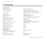
Page 46: ... bit 8 data bits 1 parity bit even 1 stop bit Addressing modes transparent Primary secondary enhanced secondary Addressing modes direct reading Primary secondary Address range primary 001 250 Address range secondary 00000000 99999999 Address range enhanced secondary 00000000 99999999 00000000 99999999 Bus mark space 41 V DC 28 V DC Detection level communication 7 mA Detection level collision 25 mA...

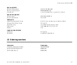
Page 47: ... Hz Power consumption Max 40 W Mechanical Operating temperature range 0 55 C non condensing installation indoors Storage temperature range 20 60 C Protection class Up to IP 67 depending on cables Dimensions 210 x 168 x 64 mm H x W x D Weight 1 kg Approvals and standards Approvals CE marking Standards EN 13757 2 EN 13757 3 12 Ordering numbers Description Ordering No M Bus Master MultiPort 250D MBM ...

Page 48: ...Kamstrup A S 5512853_C1_GB_01 2017 ...

Reviews: