


Venkon XL UL
Assembly, installation and operating instructions
37
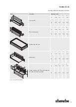
6.5.6 Condensation connection
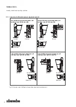
6.5.6.1
Condensation drain with natural gradient
A condensate drain provided by the customer must be connected to a condensate drain socket of the Venkon (size of drain
15 mm / 0.6 inch) and fastened accordingly. To ensure condensation drainage from the base unit, the slope must be at least 1
% without restriction and without rising pipe sections (according to DIN EN 12056; old: DIN 1986-100). Ensure that the base
unit is mounted horizontally. Should this not be possible, only install the unit with a slight slope in the condensate drain dir-
ection, otherwise condensate will remain in the main condensate tray. When connecting the condensate drain to the sewage
system, the valid regulations must be observed, such as the use of a ball siphon. The siphon must be protected from drying
out. Due to the suction effect of the fan on the condensate drain socket, it could otherwise lead to odor nuisance. Depending
on the pipe material used by the customer for the condensate drainage, vapor diffusion-tight insulation may be required.
Should a natural slope not be possible on site, a condensate pump (optional accessory) is required. Its purpose is to transport
the condensate to collection or discharge facilities located at a higher level.
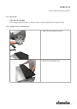
6.5.6.2
Condensate drainage using a condensate pump (accessory)
The water is drawn off by the condensate pump and discharged along a hose (supplied loose) connected on the pressure
side. Depending on conditions on site, the water can be discharged into drainage lines, possibly with a trap connection.
In the event of a fault with the condensate drain, the water level will continue to rise until the float switch triggers an alarm
contact. The contact can be analysed by external signalling devices.
We would recommend automatically terminating cooling operation, possibly with a shut-off valve, if the alarm contact is
triggered to prevent the condensate tray from overflowing.
Condensation drain
Drainage of condensation from the condensation pump has to be provided along a natural gradient with an adequate
cross-section (minimum 1/2"). Increase the cross-section of the line with longer condensate lines.
Check whether the condensation line needs to be insulated to prevent the build-up of condensation along the line.
Do not use a rigid transition to the on-site condensation drain, as this lengthens the pump's pressure hose. We would re-
commend free overflow into a trap.
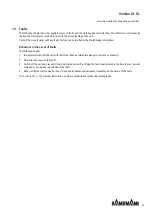
Installation, cabling of the condensation pump (accessory)
The condensate pump needs a separate power supply 230 V/50 Hz. We would generally advise against connecting it via the
room thermostat, as residual condensate could be produced after it has been switched off. Additional wires are needed to
analyse the alarm contact.
Use the following types of cable:
Mains supply: NYM-J, 1.5 mm²
Alarm contact: The cable for the alarm contact depends on the kind of alarm analysis used (e.g. shielded cable).
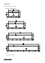
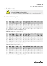
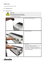
260 / 10.2
268 / 10.6
Fig. 15: Installation height with factory-mounted condensate pump
Note: With the condensate pump installed at the factory, the minimum installation height increases from 260 mm to 268 mm
or from 10.2 inches to 10.6 inches.
Summary of Contents for Venkon XL UL
Page 2: ......


