


Venkon XL UL
Assembly, installation and operating instructions
28
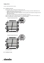
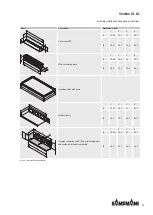
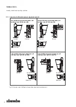
6.5.1 Connection to the pipe network
The supply and return connections are located on the left or right side of the unit, as seen in the direction of the air flow.
The piping must be laid in such a way that no mechanical stresses are transferred to the heat exchanger and the accessibility
of the unit during maintenance and repair work is not impaired. Proceed as follows when connecting the unit hydraulically:
Before installing the piping provided by the customer and the hydraulic connection of the base unit, shut off the heating/
cooling medium and secure it against unintentional opening, otherwise there is a risk of scalding due to escaping heat-
ing medium!
With cooling equipment, there is danger to the user from cold and danger to the environment when glycol is used. Fol-
low appropriate safety precautions.
Remove the protective covers from the supply and return pipes.
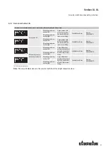
For 2-pipe:
Remove red protective caps from ¾“ connection.
For 4-pipe:
Remove red protective caps from ¾“ connection.
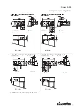
In the case of cooling operation, install pipes and, if necessary, valves directly above the protruding condensate tray in
order to drain the condensate occurring on the pipes into the tray during cooling operation.
Seal and screw in the connections. Secure the connecting nut against shearing and twisting.
When connecting the unit to the piping provided by the customer, it is essential to hold the water connections in place
with a suitable tool!
Ensure venting of the pipelines by the customer.
The connections of the heat exchanger are made in ¾“ with NPT female thread.
Use suitable insulating material, for cooling units use diffusion-tight insulating material.
After completion of all connection work, all screw connections must be retightened and checked for tension-free as-
sembly.
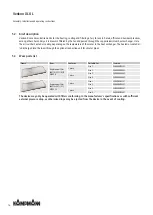
Summary of Contents for Venkon XL UL
Page 2: ......


