Venkon
Assembly, installation and operating instructions
50
7.3
Electromechanical control, Venkon EC
7.3.1 Connection (*00M or 01M), Venkon EC
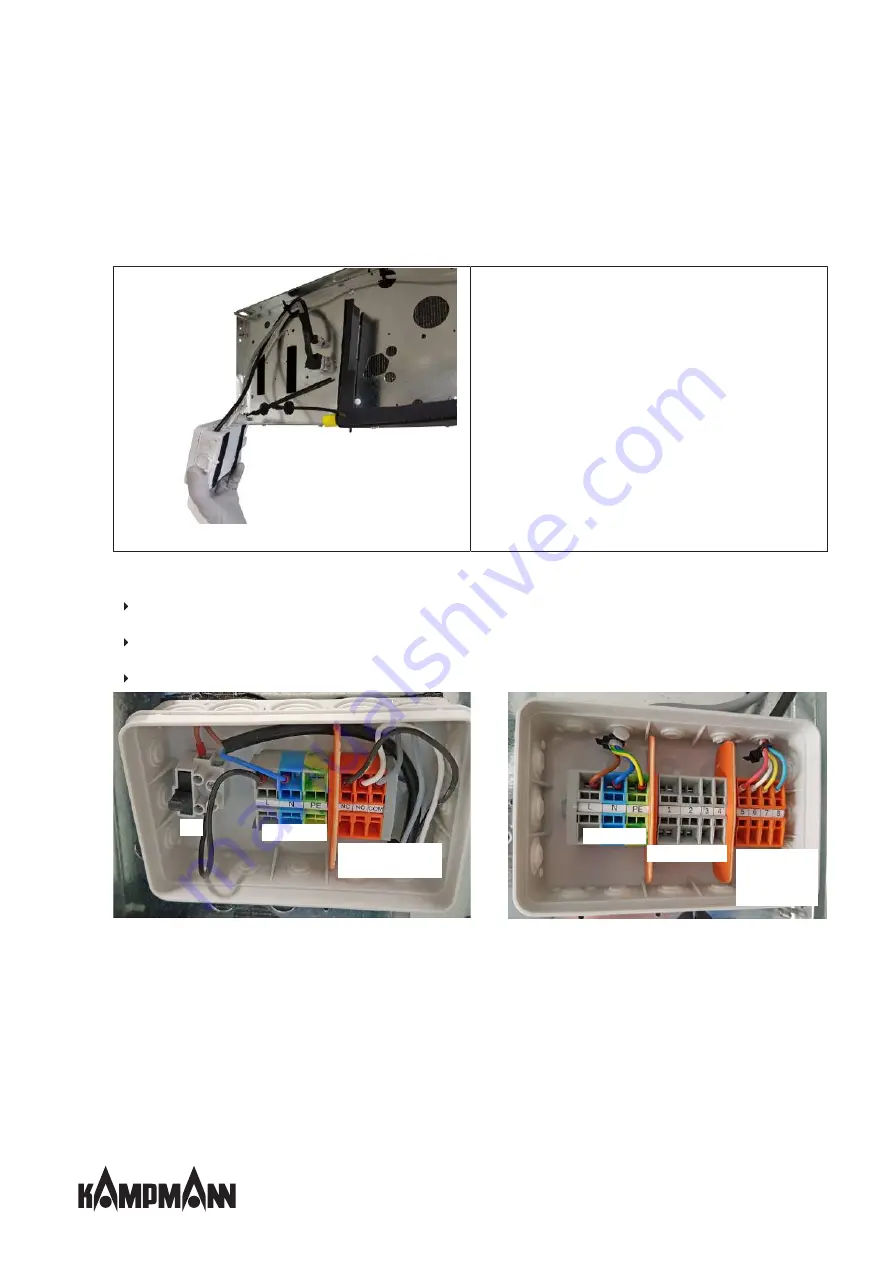
Fig. 45: Remove junction box from the Velcro strip
The junction box for electromechanical control (AC and EC) as
well as the junction box for the condensation monitor can be
electrically installed separately from the side panel of the ba-
sic unit by Velcro fitting. Simply remove the plastic lid to open
the junction box.
Description of wiring
Factory-fitted actuators are wired to the terminal. If no valve actuators are factory-fitted, support terminals are available
for on-site valve actuators.
The speed of EC fans used is continuously variably controlled by a 0 – 10 V DC signal. The “intelligent” motor electronics
detects any possible motor fault and automatically switches off the fan.
Control version *01M:
A potential-free “motor fault signal” contact is also available for external evaluation.
Power supply
Condensate alarm
message
Fuse
Junction box for condensation monitor
Junction box for Venkon EC
electromechanical
Power supply
Valve actuator(s)
Speed and,
motor fault
signal,
if required
Fig. 46: Junction boxes Venkon EC
Summary of Contents for Venkon Series
Page 2: ......
Page 86: ...Venkon Assembly installation and operating instructions 86 13 Certificates...
Page 90: ......
Page 91: ......


