


24
air pressure in the system. The warning
buzzer will shut off after air pressure has
reached 70 P.S.I.. (See page 21)
If the warning light and buzzer do not shut
off at least 5 minutes after start-up, shut
the engine down and determine why the
air system is not charging.
If the Low Air indicator light or buzzer
indicates a loss of air pressure while
driving, the vehicle should be stopped
immediately. The vehicle should not be
operated until the air system is repaired
and functioning properly.
Danger - Do not operate
the vehicle if the air brake
system is not working
properly.
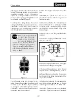
SERVICE BRAKES
The Service Brake system is controlled by
a foot operated treadle valve (foot pedal)
in the cab. This is the left hand pedal, lo-
cated to the right of the steering column
(Fig. 1, page 24). The amount of foot
pedal pressure determines the amount of
air pressure delivered to the brakes. The
more pressure on the treadle valve (pedal),
the more braking force applied. The ser-
vice brakes should be applied in smooth
constant applications. They should not be
pumped or fanned while slowing or stop-
ping the vehicle. Even in an emergency
stop situation, the service brakes should
not be rapidly “pumped”.
NOTE - Air brakes do not respond like the
brakes in a car, and pumping them in an
emergency stop is not advised. Rapidly
“pumping” the brakes is more likely to use up
all of the air in the system and cause the spring
brakes to apply and lock the rear wheels. This
will cause an out of control skid.
Figure 1
A Accelerator Pedal
B Brake Treadle/Pedal
The service brakes are the primary brakes
used by the operator. The service brakes
require air to operate. If there is insuffi-
cient air in the system, the service brakes
will not operate.
The spring brakes are used for parking
the vehicle. They are also called the
parking brakes because the parking brake
control applies the spring brakes. The
spring brakes use the mechanical force
of a spring to operate. They do not need
air to operate, but they do need air to be
released. If there is a loss of pressure in
the system, these brakes will automatically
apply. This is why the spring brakes are
sometimes called “emergency” brakes.
Remember, if there is no air in the system
the spring (parking) brakes will not fully
release.
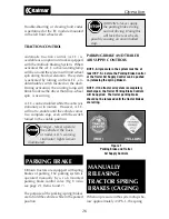
LOW AIR PRESSURE INDICATORS
When air pressure in the brake system is
below 70 P.S.I., the warning buzzer will
sound and the LOW AIR warning indica-
tor on the dash panel will light up. The
air pressure gauges should indicate low
Operation
B
A
Summary of Contents for Ottawa
Page 1: ......
Page 17: ...16 Operation...