8
101901 RevD
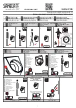
Step 4 - Lift Rod Installation
Unscrew the
nut
from the
drain body
shaft.
Wrap the 2/3 of the
drain body shaft
threads with
thread
sealant tape
.
Insert the
horizontal rod
into the
drain body shaft
and screw
the
nut
back in position with the
gasket
. In limited space, cut
the
horizontal rod
as needed.
Slide the lift block into the
horizontal rod
. Slide the
lengthened lift rod
into the
connecting block
and screw the
lengthened lift rod
into the
rod
under the faucet.
Adjust the
connecting block
position so that the
horizontal
rod
and the
lift rod
are perpendicular and tighten the
screws
to fix the
connecting block
in position (fig. 4.1).
Check the
pop-up drain stopper
operation by moving up and
down the
knob
behind the faucet; the
drain stopper
must
completely close to prevent water from flowing. As required,
adjust the
connecting block
position on the
rods
(fig. 4.2) or
follow the steps in the
Troubleshooting
section to adjust the
stopper
height.
Étape 4 - Installation de la tige de levage
Dévisser l’
écrou
de la tige du
corps du drain
.
Couvrir les deux tiers des filets de la tige du
corps du drain
à
l’aide de
ruban d’étanchéité pour filetage
.
Passer la
tige horizontale
dans le corps du drain et revisser
l’
écrou
avec le
joint
.
Insérer le
coulisseau
dans la
tige horizontale
. Insérer
l’extrémité de la
tige de levage longue
dans le
bloc
d’ajustement
et visser la
tige de levage
sur la
tige
sous le
robinet.
Ajuster la position du
bloc d’ajustement
pour que la
tige de
levage
soit perpendiculaire à la
tige horizontale
et resserrer
les
vis
pour fixer le
bloc d’ajustement
en position (fig. 4.1).
Vérifier le fonctionnement du
bouchon du drain
en soulevant
et en abaissant le
bouton
derrière le robinet ;
le bouchon
doit se fermer complètement de manière à empêcher
l’eau de s’écouler
. Au besoin, réajuster la position du
bloc
d’ajustement
sur les
tiges
(fig. 4.2) ou suivre les étapes
décrites à la section
Guide de dépannage
pour corriger la
hauteur du
bouchon du drain
.
Fig. 4
Fig. 4.1
A
A
Ruban d’étanchéité pour filetage
Thread sealant tape
Fig. 4.2
Summary of Contents for Cite BF1161-120
Page 13: ...13 101901 RevD Notes...


