


Kahlenberg
Instructions, M-522, Software Rev. R., Rev. 10/7/2019
Page 7 of 10
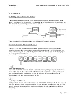
Horn Select Button
The Horn Select Button will select which horns are to be activated by the automated signal. Aft
Horn, Forward Horn, or Both Horns (if installed) can be selected by repeatedly pressing the
button. Red LEDs will illuminate on the corresponding buttons above the ship graphic that
represent each horn to indicate the current selection.
Morse Light On/Off Button
The Morse Light is activated by the automated restricted visibility code when selected by this
button. The Red LED in the Morse Button above the ship graphic will illuminate when it is
“On”.
Automatic Restricted Visibility Code Selections:
Pressing any of the Restricted Visibility Code Selection buttons will choose the automated
restricted visibility signal to be produced as follows per IMO COLREGS, RULE 35:
One Prolonged Signal______________________Making Way through Water (Underway)
Two Prolonged Signals____
Underway But Stopped and making no way through the water
One Prolonged Signal and Two Short Signals______________Vessel not under command
One Short Signal, One Long Signal, One Short Signal_______________Vessel At Anchor
**This signal will only operate at 60 seconds intervals per Rule 35g, regardless of cycle
interval selected.
One Prolonged Signal and Three Short Signals__________________Vessel being Towed
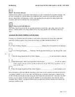
Once automatic restricted visibility signaling is activated, it will continue until turned off by the
“Automatic On-Off” switch. Any other At-Will button, externally connected or internal to the
M-522 will discontinue the automated signal which must be restarted at the “Automatic On-Off”
switch, or at a remotely located “Automatic On-Off” switch if installed. The General Alarm,
Abandon Ship, Anchor, Aground or Maneuvering Signals if activated will also discontinue the
restricted visibility code.


