Kahlenberg M-522 Installation, Operation And Maintenance Instructions Download Page 6

Kahlenberg 

Instructions, M-522, Software Rev. R., Rev. 10/7/2019 


Page 6 of 10 


3.)


OPERATION


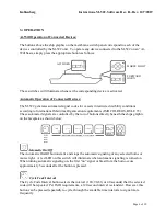
At-Will Operation of Connected Devices: 


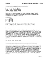
The buttons above the ship graphic on the membrane switch panel correspond to each of the 

devices controlled by the M-522 unit.  To operate any device connected to the M-522 on an “At-

Will basis, simply press the appropriate button as follows: 


These switches will illuminate whenever the corresponding device is activated. 


Automatic Operation of Connected Devices: 


The M-522 generates automated signal codes for vessels in restricted visibility conditions 

according to International Maritime Organization requirements (IMO COLREGS, RULE 35).  

These automated signals are controlled by the row of buttons directly beneath the ships graphic 

on the faceplate as shown below: 
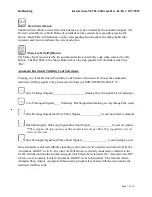


Automatic On/Off


The Automatic On/Off button starts and stops the automatic signaling of any selected horns or 

morse light.   A red LED on this switch will illuminate when automatic signaling is turned on.  

When turning automatic signaling on, the first “on” signal or blast from the horn occurs 

approximately 5 seconds after the button is pressed. 


Cycle Code Interval


The Cycle Code Interval button selects the interval (120, 90, 60, or 40 seconds) that the selected 

code will be repeated.  Per IMO requirements, a 120 second interval is standard.  However, this 

button can be pressed repeatedly to cycle through the available time intervals to signal more 

frequently. 


AFT HORN 


MORSE LIGHT  


FORWARD 

HORN 

Summary of Contents for M-522

Page 1: ...operated in conjunction with external Sound Surveillance Systems and or Public Address systems Multiple M 522 units can be utilized on the vessel and will communicate with each other in cases where mu...

Page 2: ...Terminal 33 PA Interrupt 1 Terminal 34 External Momentary Pushbutton for Automated Horn Signals 1 Terminal 29 Negative D C Connection External 24 VDC Power 1 Terminals 35 36 Additional Contact Closur...

Page 3: ...e in conjunction with the M 522 such as external General Alarm Systems Setting SW1 Switches On the internal circuit board of the M 522 there is a switch assembly labeled SW1 Settings on this switch as...

Page 4: ...ther or not the M 522 Controller will allow the aft and forward horn to sound simultaneously Per IMO Rules where two ship whistles are installed a distance greater than 100M apart they must not be sou...

Page 5: ...uld be connected per Drg 3 6749 utilizing shielded cables and wire gauge per electrical requirements as given below Power Source Required 100 240 Volt A C 50 60 Hz 1 Ph AND OR 8 30 Volts D C Electrica...

Page 6: ...s IMO COLREGS RULE 35 These automated signals are controlled by the row of buttons directly beneath the ships graphic on the faceplate as shown below Automatic On Off The Automatic On Off button start...

Page 7: ...ows per IMO COLREGS RULE 35 One Prolonged Signal______________________Making Way through Water Underway Two Prolonged Signals____ Underway But Stopped and making no way through the water One Prolonged...

Page 8: ...Drg 3 6749 for connection locations These external push buttons make contact for 24 Volts to the M 522 input from a remote power source An optional 100 240 VAC to 24 VDC power supply model M 800 is a...

Page 9: ...f installed on the vessel See Drg 3 6749 for connection location 4 CARE AND MAINTENANCE The M 522 Sound and Light Control is a solid state device designed to provide many years of maintenance free ope...

Page 10: ...e 10 of 10 5 DRAWING REFERENCES Outline Dimensions 3 6728 Parts List 3 6729 Wiring Diagrams 3 6749 General or as Specified by Contract Kahlenberg Industries Inc 1700 12th St P O Box 358 Two Rivers WI...

Page 11: ......

Page 12: ......

Page 13: ......

Page 14: ...n Active Auto Code Red LED Timer 120 Seconds Timer 90 Seconds Timer 60 Seconds Timer 40 Seconds Code 1 LED Byte 3 Bit 0 Bit 1 Bit 2 Bit 3 Bit 4 Bit 5 Bit 6 Bit 7 Code 2 LED Code 3 LED Code 4 LED Code...

Page 15: ...tion Message Number Time Offset ms Bus Type ID hex Reserved Data Length Code Data Bytes hex FWD HORN 171 5383 214 1 Rx 00000002 00 8 02 00 00 00 00 00 00 00 172 5408 895 1 Rx 00000001 00 8 01 00 08 00...

Reviews: