


7.7.3
Ethernet connection
NOTE
The connection plug of an RJ45 cable is larger than the opening of an M25 cable fitting when it is installed.
For this reason, remove the sealing insert before installation and thread the Ethernet cable outside of the
cable fitting through the sealing insert.
NOTE
Use a suitable category 5 network cable. The maximum length of a network segment is 100 m. Ensure that
the cable is correctly assigned. The Ethernet connection of the device supports auto-sensing. You can use
both crossed and 1:1 protectively-wired Ethernet connection cables.
↻
Connecting cable inside the device.
1 Plug in an Ethernet cable at one of the two Ethernet ports on the communication circuit board.
2 Lay the Ethernet cable correctly in the lower AC supply area and loosely fasten it using the cable ties provided.
3 Tighten the cable fittings [[ W_29 / 4 Nm].
Connecting the device to the network
↻
Connect the Ethernet cable to the device.
1 Connect the Ethernet cable to the network or a computer.
2 Configure the Ethernet settings and the web server in the Settings menu.
7.7.4
Connecting the S0 output
An S0 pulse output is located on the communication board. Use this output to control accessories such as a large display,
for example. The pulse rate of the S0 output is adjustable in the menu.
Connecting the S0 output
1 Unscrew the cable fitting.
2 Pass the connection cable through the cable fitting.
3 Attach the connection cables to the terminal clamps.
4 Tighten the cable fitting.
NOTE
Ensure that the DATA+ and DATA- wires are properly connected. Communication is not possible if the wires
are reversed!
7.7.5
Connecting the RS485 Bus
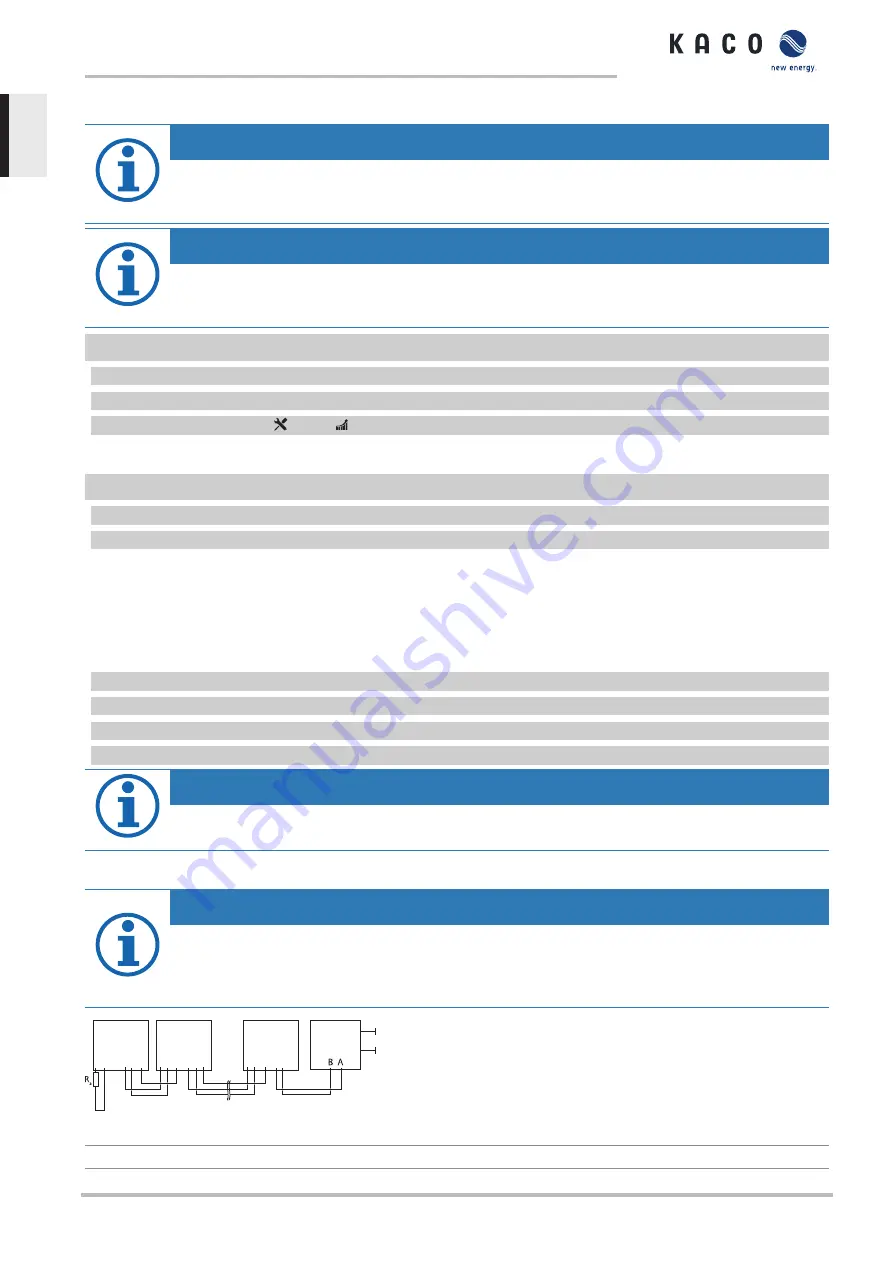
NOTE
Ensure that the DATA+ and DATA- wires are properly connected. Communication is not possible if the wires
are reversed! Different manufacturers do not always interpret the standard on which the RS485 protocol is
based in the same way. Note that the wire designations (DATA- and DATA+) for wires A and B may vary
from one manufacturer to another.
A B
GND
A B
GND
A B
GND
A B
GND
A B
GND
A B
GND
4
1
2
2
3
5
Fig. 35:
RS485 interface wiring diagram
1
Inverter, terminal unit
4
Communication
Powador 30.0-72.0 TL3
Page 30
EN


