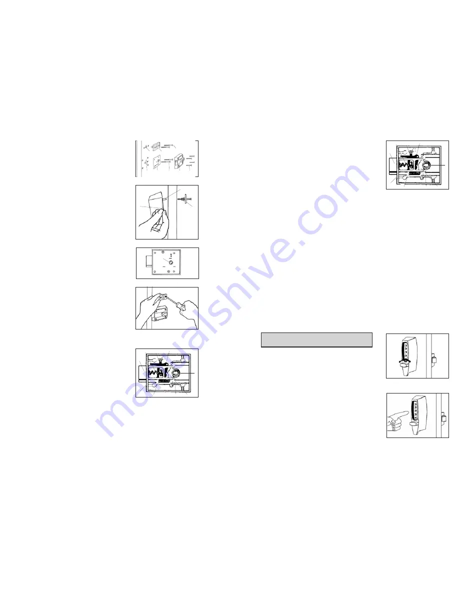
7
6
E-2
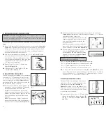
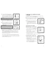
While holding the lock firmly against the out-
side of the door, use two round head thru-
bolts (
D
) to secure the inside reinforcement
plate (
C
). Finger tighten only.
E-3
Use a thin object
A
(screwdriver) to align tail-
piece (
X
) with the horizontal slot of the combi-
nation change assembly (
G
)
(See Figure 5-3)
.
Attach the combination change assembly (
G
)
with two flat head thru-bolts (
H
). Finger tight-
en only
(See Figure 5-2).
E-4
Securely tighten the two thru-bolts (
D
) to
reinforcing plate (
C
)
(See Figure 5-2).
E-5
Position the cam on the inside rim deadlock-
ing
(See Figure 5-4)
. Turn cam to the right
(clockwise) manually until it stops.
E-6
Mount the inside rim deadlocking latch (
E
) so
that tailpiece
Y
is engaged in the vertical posi-
tion. Secure evenly with four screws (
F
).
(See
Figure 5-2).
E-7
Lightly push the combination change assem-
bly down and secure screws evenly
(See
Figure 5-5).
F. REVERSING THE LATCH
The model 7106 lock is packaged for an inward
opening door. For an outward opening door, the
latch must be reversed.
F-1
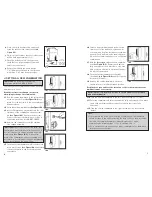
With the latch extended (
A
), remove the two
backplate screws from the underside of the
inside rim deadlocking latch. Remove the
backplate using a small flat blade screwdriver.
F-2
Carefully remove the latch spring (
B
) and
auxiliary latch spring (
C
) with a small flat
blade screwdriver.
F-3
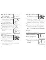
Press the latch and auxiliary latch (
D
) into the
case to the stop position
(See Figure 6-1)
.
F-4
Lift the auxiliary latch up and out. Reverse the auxiliary latch bevel and
place it back into the case. Hold the auxiliary latch down and slide it for-
ward so it will project
3
⁄
8
" (10 mm) beyond the case front and hold the
auxiliary latch lever (
E
) out of the way.
F-5
While holding the auxiliary latch as instructed
in step 4, place the latch in the case with the
bevel in the same direction as the auxiliary
latch. Make sure the latch legs (
F
) are caught
on the ears of the turn knob lever (
G
)
(See
Figure 6-2)
.
F-6
Push the latch and auxiliary latch forward
to the stop position so that they are fully
extended
(See Figure 6-2)
. Insert the latch spring (
H
) (large opening of
spring) towards back of latch and the (small opening of spring) against the
spring seat. Insert one end of the auxiliary latch spring into the back of the
auxiliary latch and place the other end of the spring against the spring
seat.
F-7
When the springs are installed, the auxiliary latch lever (shaded area in
Figure 6-2
) should be in the position shown in
Figure 6-2
.
F-8
If the cam (
I
) falls out, replace it in the thumbturn hole with the circular
opening facing up. Place the backplate onto the case with the letters fac-
ing up towards you, and fasten with two screws removed in step 1. Check
the lock for freedom of movement by depressing the latch and auxiliary
latch into the lock case, then make sure that the latch and auxiliary latch
return back to their original fully extended position
(See Figure 6-2)
.
Install the Lock
Follow Steps E-1 to E-7.
G. CHECKING THE LOCK’S OPERATION
Important:
The following steps must be
performed while the door is open.
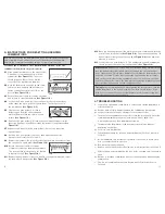
G-1
Turn the outside thumbturn to the left
(counterclockwise) until it stops, then
release it
(See Figure 7-1)
.
G-2
Press the preset factory combination (2 and 4
pressed together, release, then 3, and release)
(See Figure 7-2)
. A distinctive click must be
felt to indicate that the buttons have been cor-
rectly depressed.
A
5-3
5-5
X
5-4
A
G
6-1
A
D
B
H
E
C
F
G
I
6-2
A
D
B
H
E
C
F
G
I
7-1
7-2
5-2
A
C
D
E
F
B
G
H


