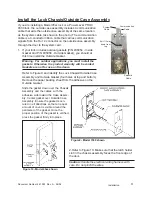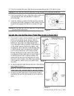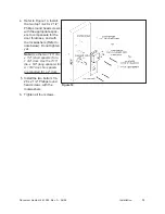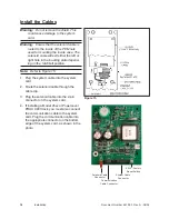
Document Number 481.093 Rev. A - 06/04
8
For all doors:
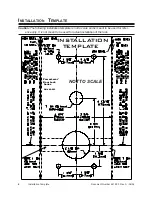
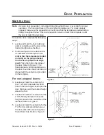
6. Locate and mark the center for the
four 11/32” (8.7mm) diameter
throughbolt clearance holes. Refer to
Figure 4.
7. Locate and mark the center for the 1”
(25.4mm) diameter thru-hole for the
system cable.
8. Center punch all hole positions onto
the door.
Drill the Holes
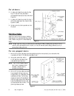
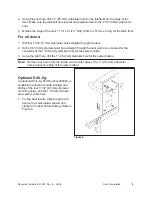
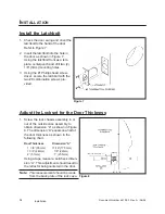
Refer to Figure 5 for summary drilling
dimensions. An optional Drill Jig is avail-
able. Refer to Figure 6 on the following
page.
Note:
Make sure the holes are drilled level and straight. When drilling through the door, be
careful not to damage the door finish. It is recommended that safety glasses be worn
during the drilling process.
For non-prepped doors:
1. Drill a 1/8” (3mm) diameter pilot straight through the door where you marked for the
centerline of the 2 1/8” (54mm) diameter hole.
2. Using the pilot hole, drill a
2 1/8” (54mm) diameter hole
straight through the door.
Note:
The 2 1/8” (54mm) diam-
eter hole in a labeled door
shall be drilled under li-
censed procedure.
3. Drill a 1/8” (3mm) diameter pilot
hole straight through the door
edge where you marked for the
centerline of the 1” (25.4mm)
diameter hole for the latchbolt
into the edge of the door. Make
sure the latchbolt hole is level
and perpendicular to the 2 1/8”
(54mm) diameter hole.
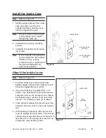
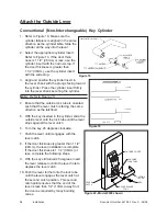
Figure 4
Figure 5
Door Preparation
Summary of Contents for PowerLever 1550
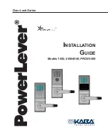
Page 1: ...PowerLever Door Lock Series INSTALLATION GUIDE Models 1550 4550 4560 PROX 9000 ...
Page 4: ...SPECIFICATIONS 22 Electronic Specifications 22 Hardware Specifications 22 TROUBLESHOOTING 22 ...
Page 28: ...Document Number 481 093 Rev A 06 04 24 ...
Page 29: ...NOTES ...
Page 30: ......
Page 31: ......

