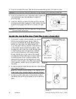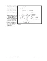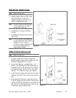
Document Number 481.093 Rev. A - 06/04
14
Install the Cables
Warning:
Do not remove the shield. This
could cause damage to the system
card.
Warning:
Ensure that the solenoid cable is
routed to the inside of the PEM nuts
used for mounting the inside case. The
solenoid cable will exit either the left or
right hole in the backing plate depend-
ing on the latchbolt position.
Note:
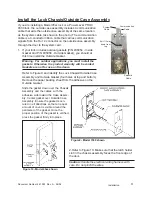
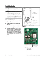
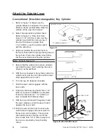
Refer to Figure 15.
1. Plug the system cable into the system
card.
2. Route the solenoid cable through the
cable clip.
3. Plug the solenoid cable into the 2-pin
connector on the system card.
4. If installing a Model 45xx or PowerLever
PROX 9000 lock, you must also connect
the communication cable to the system
card. Plug the communication cable into
the appropriate connector on the bottom
edge of the system card, as shown in the
photo.
Figure 15
Communication
Cable Connector
System Cable
Connector
SW2 - Factory
Reset Switch
Solenoid Cable
Connector
Installation
Summary of Contents for PowerLever 1550
Page 1: ...PowerLever Door Lock Series INSTALLATION GUIDE Models 1550 4550 4560 PROX 9000 ...
Page 4: ...SPECIFICATIONS 22 Electronic Specifications 22 Hardware Specifications 22 TROUBLESHOOTING 22 ...
Page 28: ...Document Number 481 093 Rev A 06 04 24 ...
Page 29: ...NOTES ...
Page 30: ......
Page 31: ......


