Kaba ILCO RAC 660G XT Installation Manual Download Page 8

PK3520_09_07 • REMOTE ACCESS CONTROLLER - 660G XT

8

4.0 System Installation Overview

NOTES: 

•   For  Installation  of  the  keypads  refer  to  the  manufacturer’s 

installation instructions.

•   The  RAC  660G  XT  provides  egress/ingress  (exit/entry) 

access  control  to  locations  where  stand-alone  locking 
devices cannot be used.

4.1 Pre-Installation Procedures

Before starting: 

•   Ensure that all cabling is available for the required wiring 

of  peripherals  as  indicated  in  the  instructions  supplied 
with  each  product  to  be  connected  and  for  the  power 
adaptor if needed.

•   Be sure to have all tools listed on the tool list in section 3.1.
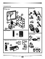
•   Be sure to have every component available as ordered for 

the 660G XT system being installed. Refer to the parts list 
in section 3.1.

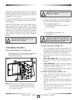
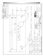
Step 1:  Identify secure location for the 

controller box 

Important:  Access to the control panel must be 
restricted to authorized personnel only. (ex: service)

!

Important:   If no AC power source is available near 
the desired control box location, a certified electrician 
must install an electrical outlet within 6 ft max of the  
660G XT system.

!

•   If  possible,  the  control  panel  should  be  mounted  at  a 

workable  height  with  clearance  to  completely  open  the 
access panel near an unswitched AC power source.

•   Make sure that the controller box can be secured to the 

wall or ceiling using the screws and anchors provided in 
the hardware bag. 

•   The controller box can be either placed horizontally in the 

ceiling or vertically on a concrete, wood, or plaster wall.

•   The temperature in the chosen location must be between 

32°F to 120°F (0°C to 49°C).

•   The controller box must be in a location sheltered against 

exterior elements, weather hazards and dripping water.

•   Do  not  use  cord  and  wall  outlets  for  mounting  of  the 

controller box. The unit must be fixed with the hardware 
supplied.

Step 2:  Identify location(s) for the keypad 

and required peripherals

For  ingress  and  egress  functions,  keypads  must  be  placed 

within  100  feet  (30m)

  from  the  controller  box.  The  keypad 

should be installed near the access door. The location should 
be obvious and ergonomically efficient to any user.

Important:  All peripherals used must be installed as 
per local building codes and legislation.

!

Keypads:

The space to use the keypad must be large enough to allow 
adequate clearance.

Remaining peripherals:

Determine the location required for any other 660G XT system 
peripherals (REX button, remote unlock, etc) and ensure that 
all required cabling is available as needed.

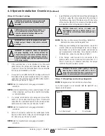
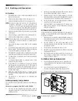
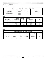
Step 3: Set the desired access delay

The  660G  XT  system  factory  default  setting  for  the  delay  on 
access devices is 3 seconds. To change the value configure 
the controller board (C) dip switch SW2 settings as per Annex 
A, Table 3.

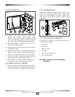
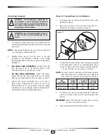
Step 4: Install strain relief

Two  strain  reliefs  (Z)  are  provided  in  the  hardware  bag  to 
secure  the  wires  leading  into  the  controller  box  and  help 
prevent the possibility of wire tampering.

Compression 
Nut

A

Figure 8

Z

NOTE: 

 The two strain reliefs (Z) provided in the hardware bag 
have different opening diameters to allow for a variety 
of  wires  to  be  routed  into  the  controller  box.  Do  not 
attempt to route an excessive amount of wires. If extra 
strain reliefs are required please contact Kaba.

Summary of Contents for ILCO RAC 660G XT

Page 1: ...INSTALLATION GUIDE Remote Access Controller 660G XT PK3520 ...

Page 2: ...ntroller box 8 Step 2 Identify location s for the keypad reader and required peripherals 8 Step 3 Set the desired access delay 8 Step 4 Install strain relief 8 4 2 Installation Procedures 9 Step 5 Mounting the controller box 9 Step 6 Connect wiring 10 Step 7 Mounting wiring keypad reader 10 Step 8 Completing the installation 11 5 0 Settings and Operation 12 5 1 Testing 12 5 2 Programing using a PA...

Page 3: ...g com Warnings and Cautions Please read and follow all directions carefully Important Carefully inspect windows doorframe door etc to ensure that the recommended procedures will not cause damage Kaba Ilco s standard warranty does not cover damages caused by installation Important The RAC 660G should always be installed in a secured room or facility with controlled access to prevent access to the s...

Page 4: ...Input Standard Tamper Alarm Input Standard Power Status LEDs feedback Standard Battery Back up Optional Kaypad Egress Optional Remote Unlock input No Audit Optional Request to Exit REX input Optional 2 0 Product Description Continued 2 2 Components Figure 2 Front Desk Non Secure Side Secure Side Remote Unlock Fire Alarm Ingress Keypad Egress Keypad Battery 12V 660G XT Power Status PULL FIRE Batter...

Page 5: ...om LED shows the power status of the optional battery back up G Cam lock with key included to provide controlled access to the enclosure and secure locking for the system 2 2 3 Battery back up optional K When fully charged the 12 VDC battery back up offers the possibility of having a high capacity battery to provide up to 4 hours of operation in the event of a power failure 2 2 4 Locking devices T...

Page 6: ... 18 AWG power cables terminated with fork crimp terminals at one end Battery back up optional includes K Battery with 2x strapping bracket 2x flat washer 8 2x split washer 8 and 2x nut 8 32 L 1x red wire gauge 18 AWG x 9 terminated with fork crimp terminals at both ends not shown M 1x black wire gauge 18 AWG x 10 terminated with fork crimp terminals at both ends not shown Single Keypad includes P ...

Page 7: ...G XT 7 3 2 Exploded View Controller Box Hardware Bag Power Adaptor Peripherals Optional Devices 5x 4x 2x 4x 3x Figure 7 Keypad Ingress P 2 x 6 or 3 x 4 Q R S U O International North American AB X AA AC Y W A G F B K C E 4x AD 2x Z 1x 1x N 2x V ...

Page 8: ...e temperature in the chosen location must be between 32 F to 120 F 0 C to 49 C The controller box must be in a location sheltered against exterior elements weather hazards and dripping water Do not use cord and wall outlets for mounting of the controller box The unit must be fixed with the hardware supplied Step 2 Identify location s for the keypad and required peripherals For ingress and egress f...

Page 9: ...s or legislations 2 Two types of power adaptors are available depending on the country where the controller box is to be installed N For international applications mainly Europe UK or Australia using 220 VAC to 240 VAC 50 60 Hz or O For North American applications using 120 VAC 60Hz CAUTION The following steps are to be done after the appropriate power adaptor is selected cables routed through the...

Page 10: ...ect as per Annex A Table 1 NOTE Refer to manufacturer s wire gauge installation selections 4 Install a 2 conductor cable from the control panel to the location of the electric strike Q or electromagnetic lock R Connect as per Annex A Table 1 NOTE Refer to manufacturer s wire gauge installation selections 5 Installthediodeacrosstheterminalsoftheelectromagnetic lock R or using the crimp connectors A...

Page 11: ...oller board C as per Annex A Table 1 4 Caution with keypad selectable for 5 or 12 volts A jumper plug is installed on one of the pins This is the default setting for 12 volt operation Incorrect voltage selectable may cause damage Refer to manufacturer s specification document provided with reader Step 8 Completing the installation 1 If the panel door was removed reinstall the door on the 660G XT e...

Page 12: ...remove the main AC power adaptor and verify proper 660G XT operation 14 The 660G XT is now ready to be Initialized and Programmed 5 2 Programming using a M Unit The controller can be programmed directly on the PCB via a PALM Steps to program the RAC with PALM 1 For step by step programming instructions refer to www kaba ecode com on line help getting started and maintenance unit 2 Set the dip swit...

Page 13: ...re 15 by hooking one end of the brackets under the anchoring slots on the side of the enclosure and the other end over the threaded posts 6 Install in sequence the flat washers split washers and nuts tightening as needed 7 Connect the wires from the power supply B to the battery K ensuring that the red wire connects to the terminal and the black wire connects to the terminal 8 Reconnect the power ...

Page 14: ...or Europe UK Autralia 24 VDC 126 511939 For North America 24 VAC 062 511929 Unswitched AC Power Source 1 2 3 4 5 Key Override Key switch not supplied by Kaba D Remote Unlock T Diode 12V GND 1 2 3 1 2 3 1 2 3 1 2 3 1 2 3 1 2 1 2 3 4 1 2 3 4 1 2 3 4 1 2 3 1 2 3 4 1 2 3 4 See NOTE IMPORTANT Read manual before installation or maintenance of the unit P2 Keypad Egress Garage Door Opener Remote Access Co...

Page 15: ...18 2 GND S REX J8 3 REX Q Strike or J18 3 FIRE ALM BLACK J8 4 GND R Maglock J18 4 GND BLACK D Key Override J7 3 NO V Garage Opener J19 1 COM J7 4 GND Q Strike or J19 2 NC R Maglock J19 3 NO Note Connections required are dependant on system options purchased Note Part numbers indicated subject to change Please refer to ordering guide for current numbering Table 1 Table 2 PCB Status LED s LED Descri...

Page 16: ...n Power Supply ID Wire Color LED LED Power Status AC Fall 1 NC ORANGE N A N A RED LED Battery Status LOW BAT 1 NC YELLOW DC OU 2 RED N A N A RED Caution Red wire jack between both positive terminals of each LED also included Table 5 Table 6 Controller Board C to Power Supply B Description Wire Color Controller ID Power Supply ID DC Power RED J16 1 12V DC OUT 2 BLACK J16 2 GND DC OUT 1 AC Fail BROW...

Page 17: ...PK3520_09_07 REMOTE ACCESS CONTROLLER 660G XT 17 6 0 Annex B Drilling Template ...

Page 18: ...PK3520_09_07 REMOTE ACCESS CONTROLLER 660G XT 18 6 0 Annex B Drilling Template ...

Page 19: ...ly RAC 4XT enclosure s panel door Verify the wiring polarity to the battery If correct the battery may be Battery Status LED is OFF discharged After charging for a few hour the Battery Status LED should turn green Full charge may take up to 12 hours If the Battery Status LED is still OFF after 12 hours the battery may need to be replaced All RAC 4XT LEDs are OFF Verify that the DC ON LED on the po...

Page 20: ... lock is in not Passage Mode If the Locking Device Relay LED D31 on the RAC 660G controller is OFF Verify that the Bypass switch is not active Bypass LED D21 is OFF Verify that the Fire Alarm input not active Input contact closed Fire Alarm LED D47 is ON Verify the wiring to the locking device Locking device does not unlock If the Locking Device Relay LED D31 turns on Verify that the Fire Alarm in...

Page 21: ...ming mode The 660G controller must still be in programming mode with LED D45 blinking when the Program or Audit command is selected on the M Unit Verify that the M Unit is pointing toward the infrared Transceiver D12 located beside the DIP switch SW2 during programming and auditing The distance between the M Unit and the 660G controller should be a few inches 3 to 6 inches If the RAC 660G XT is no...

Page 22: ... 1 800 906 4526 Customer Service T 1 877 468 3555 F 514 735 6589 General Information www ilcolodging com Online Consumable Orders www keycard com To access all of our easy steps please visit our Support Website http connect kabalodging com Printed in Canada PK3520_09_07 ...

Reviews: