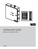


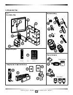


PK3520_09_07 • REMOTE ACCESS CONTROLLER - 660G XT
12
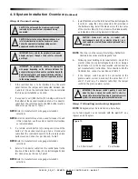
5.0 Setting and Operation
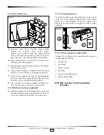
5.1 Testing
1. If not already done, connect the AC power adaptor, and / or
turn on the AC current.
2. Verify that the Power Status LED on the panel is On.
3. Verify that the Battery Status LED on the panel is On.
NOTE:
The battery status LED may be off if the battery is
completely discharged, or if the connections are
reversed. If it is Off, verify the polarity of the battery
connections. A properly connected battery may take up
to 12 hours to fully charge and for the LED to turn on.
4. Verify that the D43 LED on the controller board (C) blinks
continuously.
5. Activate the Bypass switch, SW3 on the controller board (C).
6. Verify that the locking device is activated.
NOTE:
If the locking device is not activated, verify that the Fire
Alarm input is properly connected, or a jumper wire is
connected.
7. De-activate the bypass switch, SW3 on the controller
board (C).
8.
To test the kaypad reader enter a valid code. Verify that
the door unlocks. The unlock time will correspond to the delay
set by the DIP switches as per Annex A, Table 4.
9. If the 660G XT is equipped with a second keypad, enter a valid
code at the second keypad and verify that the door unlocks.
10. If a REX button is connected, press it and verify that the
door unlocks.
11. If a Remote Unlock button is connected, press it and
verify that the door unlocks.
12. If the 660G XT is connected to a fire panel and the
electromagnetic lock powered by the 12 VDC output of
the 660G XT, verify that the electromagnetic lock or a
fail-safe electric strike is deactivated when the fire alarm
is active (open input).
13. When the optional battery backup is charged, remove
the main AC power adaptor and verify proper 660G XT
operation.
14. The 660G XT is now ready to be Initialized and
Programmed.
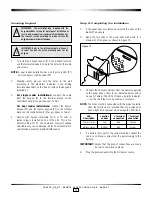
5.2 Programming using a M-Unit
The controller can be programmed directly on the PCB via a
PALM.
Steps to program the RAC with PALM:
1. For step by step programming instructions, refer to
www.kaba-ecode.com on line help getting started and
maintenance unit.
2.
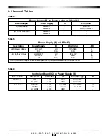
Set the dip switch SW2 bank (OFF,OFF,OFF,OFF) refer to
Access Delay Table SW2, Table 3, Annex A.
3.
Toggle any one of the Four SW2 switches to ON. LED
D45 should blink to indicate that the 660G XT is ready to
communicate when complete LED D41 should be on.
4.
On the PALM open the Oracode application software,
select Door List, choose your door.
5.
Hold the PALM in close proximity to D12 located near
SW2 and tap “Program” on the PALM. When complete
LED D41 should be on.
5.3 Reset to Factory Default
In the event the Door or Site ID of the premise is changed or a
problem is suspected with the current configuration, the 660G
XT will reset to default.
1. Note down the current DIP switch bank SW2 settings on
the controller board (C) as this is the current delay setting
for the peripherals used.
2. Set the switches on DIP switch bank SW2 on the
controller board (C) to CFG #16 (OFF, OFF, OFF, OFF) as
per Annex A, Table 3.
3. Verify that the initialization LED (D41) is OFF.
4. 660G XT is ready to be programmed. Refer to steps How
to program the RAC 5.1.
5. Set the DIP switch positions back to the chosen access
delay settings as noted above, or reset based on values
shown in Annex A, Table 3.
5.4 Battery Back-up Replacement
1. Prior to replacing the battery back-up, write down the
color and location of the two wires and the orientation
of the battery;
2. Turn off the main AC power to the 660G XT or
disconnect the power adaptor from the wall outlet.
3. Disconnect the wires (black and red) on the battery;
Figure 15