


PK3520_09_07 • REMOTE ACCESS CONTROLLER - 660G XT
5
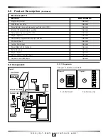
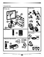
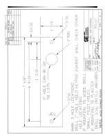
2.2.2 Controller box
Figure 5
G
F
K
H
B
A
E
C
(A) Enclosure with cover; metallic frame which
contains the controller board, power supply,
optional relay expansion board and optional battery
back up. Knockouts are available on 3 sides of the box to
give a wide range of possible installation configurations.
(B) Power supply/charger; to provide the DC power to the
controller board and peripherals.
(C) Controller board; main board that controls all the features
of the 660G XT system.
(E) Tamper switch; attached to the 660G XT controller box to
generate an alarm if the box is opened during operation.
(F) Two LEDs are available on the cover; the top LED indicates
the status of the power supply and the bottom LED shows
the power status of the optional battery back-up.
(G) Cam-lock with key; included to provide controlled access
to the enclosure and secure locking for the system.
2.2.3 Battery back-up (optional)
(K) When fully charged, the 12 VDC battery back-up offers the
possibility of having a high-capacity battery to provide up
to 4 hours of operation in the event of a power failure.
2.2.4 Locking devices
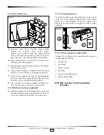
The 660G XT provides one relay output that can be used to
control one of the following locking devices, either Electric
Strikes (Q) or Electromagnetic Locks (R) or Garage Door
Opener (V). The relay output can supply 12V, 075A to locking
peripherals.
Figure 6
Q
R
V
2.2.5 Other optional components
The 660G XT is a flexible Access Control Solution and can be
combined with the following:
• Key override
• Exit Devices
• Motion Detectors
• Panic Bars
• Request to Exit (REX) button
• Remote Unlock Button
NOTE: Refer to section 4 for further installation
information.