Installation Manual
Installation
31
k2evo702 - 201610
Kaba c-lever and variants
4.5
Installing the internal fitting
NOTICE
Danger of damage to electronic components from electrostatic discharge.
If electronic printed circuit boards and components are handled incorrectly, damage
may occur which leads to their complete breakdown or sporadic faults.
•
When installing and repairing the product, the general ESD protective measures
are to be observed.
4.5.1
c-lever standard variant
Requirement:
•
Outside shield installed
•
Centring sleeve positioned in outside shield
•
Antenna cable (13) laid
•
Mortise lock and lock cylinder installed
Procedure:
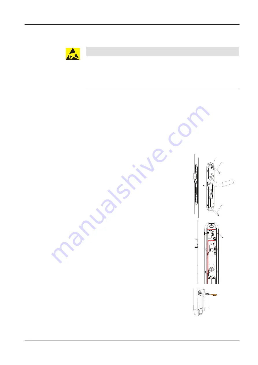
1.
Note: do not trap the antenna cable.
Place the internal fitting with the inside lever handle
on the spindle and lock cylinder (50).
24
13
24
50
2.
Note: tightening torque max. 2.5 ± 0.5 Nm.
Secure the internal fitting and outside shield using
two fixing screws (24).
3.
4.
Insert the antenna cable plug into the socket (59) of
the e-module.
Insert batteries if necessary.
Note: observe the bat-
tery polarity. Failure to do so could destroy the
electronics.
59
5.
If batteries are already inserted, remove the contact
protection film.
6.
Slip the
between the
batteries.


