RS232 /GPS OPTION
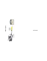
With the RS232 option the RMD-1 Control Box can be connected to
any computer or data recorder equipped with an RS232 input. The
specification of the interface is as follows: 8 bit, 4800 baud rate, 1
stop bit, and no parity bit.
The GPS/Loran C interface allows the ships position information to
be input into the RMD-1. The RMD-1 then reformats the information,
combines it with the signal strength reading from the search coil, and
sends it to an external computer via the RS232 interface.
Any GPS or Loran C receiver equipped with a NMEA 0183 output
can be used with the RMD-1. If you are not sure if your receiver has
NMEA 0183 output, check its manual or call the manufacturer. You
may find that you have to tell your GPS receiver to send out the 0183
information (refer to your GPS manual). If given a choice, select
0183A or 0183C format. Both versions include the latitude/longitude
message format called GLL. The RMD-1 can also receive the
message format called GGA, if the message GLL is not available.
The RMD-1 automatically checks for the presence of either mes-
sage on power-up.
The sample message sent on the RS232 interface is as follows:
Position 4151.745353, N, 07102.394576, W <cr>
RMD= 3270mv <cr> <cr>.
Where the "Position" is the latitude and longitude coordinates from
the GPS or Loran C receiver and "RMD" is the detection signal
strengths expressed from 0 to 5,000 millivolts (0 to 5.000 volts). The
complete message is repeated once per second.
If a GPS or Loran C is not being used, or if the GPS or Loran C
message is not being properly received by the RMD-1, the message
will be as follows:
NO POSITION AVAILABLE <cr>
RMD = 3270mv <cr> <cr>.
4
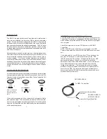
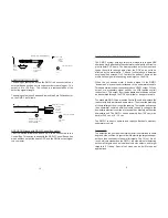
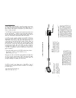
UNDERWATER HOUSING:
Contains downstairs electronics board.
Can be powered from surface Control
Box (standard) or from local ROV power
( 9-36 vdc at 8 w). Electronics board can
be removed from housing and mounted
in ROV. Electronics board output is
RS232, or analog, or a proprietary sig-
nal to surface Control Box (standard).
SURFACE CONTROL BOX:
Contains switches and controls
for operating the system. When
metal is detected by the coil, the
meter in the Control Box swings
up and the audio alarm sounds
off. Control Box also has an op-
tional RS232 and analog output
for computer or chart recorder
connection. System can be op-
erated without the Control Box
by applying power directly to the
underwater housing.
J
W
F
I
SH
ER
S
MF
G
IN
C
BE
RK
L
E
Y
,
MA
0
2779
65
A
N
T
H
O
N
Y
S
T
V
I
S
U
A
L
D
E
T
E
CT
I
O
N DI
S
P
L
A
Y
PO
W
E
R
AU
D
I
O
Underwater
Housing
Up to a 1,000 foot of cable
Surface Control
Box
OutPut
(RS232 or Analog)
Input Power
(120/240 vac or 9-36 vdc)
2 or 4 wires
RMD-1 SYSTEM CONFIGURATION
CABLE:
Can use umbilical cable from
ROV or a separate cable. A 4
wire cable is required if power
to the U/W housing electron-
ics is from the surface; 2
wires if power is from ROV.
COIL:
High noise immunity coil
set. Standard coil set is 10"
x 16" x 5". Larger coils are
available by special order.
Full ocean depth coils are
also available.
4 foot cable
standard


