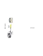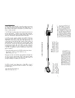
RMD-1 CONTROL BOX
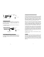
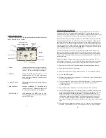
The heart of the system is the control box which contains all controls
and indicators for the system:
• Meter
Indicates the presence of metal by swing-
ing to the right. The closer the metal is to
the coil, the further it will go to the right.
• Speaker
When the meter moves past .2 , the
speaker sounds off. The higher the meter
goes, the higher the pitch (frequency) out
of the speaker.
• Volume Control
Adjusts the volume out of the speaker or
earphone.
• Earphone Jack
Accepts a standard 1/4" earphone plug
(stereo or mono). Speaker output is si-
lenced when earphones are plugged in.
• RS232 Output
With this option the RMD-1 can be con-
nected to any computer or data recorder
with a RS232 input.
MOUNTING AND CALIBRATION
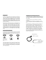
The RMD-1 has been factory calibrated for proper operation when mounted on a
JW Fishers ROV or other non-metallic host platform. In other applications, the
search coils should be mounted as far from metallic components as possible. Only
nylon or 316 stainless steel fasteners may be used near the search coils.
Before permanently mounting the search coils, test the RMD system to insure that
it will operate properly with the search coils in the chosen location. When testing,
the host platform and search coils must be clear of other metals (at least 6 ft from
the search coils). To check for proper operation, test each sensitivity setting (low,
medium, and high). In each setting, the zero adjust knob should be able to set the
meter between 1 and 2, the normal operating range. If using the RS232 output, the
reading should be close to +0.1vdc (+100mv dc).
If the above condition can not be met, try repositioning the search coils for the
lowest meter reading. Once the best location is found, secure the search coils in
the chosen position. Retest the system. If the zero adjust knob cannot zero the
meter in each sensitivity setting, complete the following procedure to calibrate the
downstairs board.
Equipment needed: Phillips screw driver, small flat blade screwdriver, DC volt
meter able to read down to 0.1 vdc. If the RS 232 output will be used, the readings
from this test may be observed on the PC display instead of the dc volt meter.
1)
Remove the (2) 4-40 x 3/8" flat head screws from the underwater housing.
2)
Slide the cable end out of the housing.
3)
Rest the circuit board on a non-metallic surface. Do not unplug any cables.
4)
Turn on the RMD system.
5)
Measure the voltage on the right pad of J2. Connect the (-) lead of the meter to
pin 2 of JP6 (green wire).
6)
Turn the trimpot R37 with the small flat blade screwdriver. Turn in the direction
that causes the voltmeter reading to decrease. DO NOT ADJUST ANY
OTHER TRIMPOTS
7)
Adjust R37 until the voltmeter or PC display reads +0.10vdc (+100mv).
8)
Test the RMD system again. The zero adjust knob should be able to zero the
meter in all sensitivity switch positions. Slowly approach the search coils from
below the 'Bottom Coil' with a metal object. The voltage should begin to
increase as the object is brought closer to the 'Bottom Coil'. Please note that
the detection envelope is non-linear. The voltage change will be very small
(50-100mv) when the object is at the outer edge of the detection envelope.
The voltage change will be greater as the object is brought closer to the search
coils.
9)
Reinstall the underwater housing and o-ring. Be sure the o-ring and its seats
are clean. Reinstall the (2) 4-40 x 3/8" flat head screws. Do not overtighten.
10
5
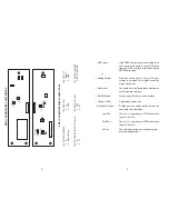
Power Cord
Speaker
Volume Control
Earphone Jack
Analog Output (option)
or
GPS Input (if RS232 option)
RS232 Output
(option)
Coil
Selection
Switch
Zero Adjust
Power On LED
Power Switch
Meter


