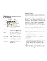
• GPS Input
If the RS232 output option is selected then
this connector is used to input GPS data
from your GPS. It is then outputted with the
RS232 data string.
or
• Analog Output
With this option a 0-2.5 vdc (or 0-5 vdc)
voltage is provided. This output tracks the
meter movement.
• Cable Jack
The cable from the "downstairs electronics
unit" plugs into this jack.
• On/Off Switch
Turns power (24vdc) on in the system.
• Power on LED
Lights when power is on.
• Sensitivity Switch
A three position switch which selects the
sensitivity of the detector:
Low Pos.
The unit is operating in LOW sensitivity
(about 1/2 of HI).
Med Pos.
The unit is operating in MED sensitivity
(about 2/3 of HI).
Hi Pos.
The unit is operating on HI sensitivity (nor-
mal operating mode).
9
6
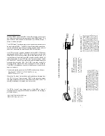
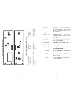
RMD-1 DOWNSTAIRS BOARD CONNECTIONS
RMD-1 DOWNSTAIRS ELECTRONICS
1
2
1
2
Bottom Coil
Top Coil
JP5
JP4
Blk
Yellow
Blk
Green
R33
R10
R16
PS1
1
2
4
3
5
1
2
Output
JP6
Green
White
R37
R56
U6
System Disable
JP1
1
2
J1
J4
J2
J3
JP7
60 Hz
50 Hz
9-36 vdc input
1
2
Black
Red
JP-1 SYSTEM DISABLE
JP-4
TOP
COIL
JP-6 OUTPUT
1. (+)
1. (+)
1.
Signal
2.
Signal
Return
2. GND
2. GND
JP-3 DC POWER INPUT (9-36 vdc)
JP-5
BOTTOM
COIL
JP-7
FILTER
JUMPER
1. (+)
1.
GND
or
SD
COMMAND
2. (-)
2. (+)


