background image

33

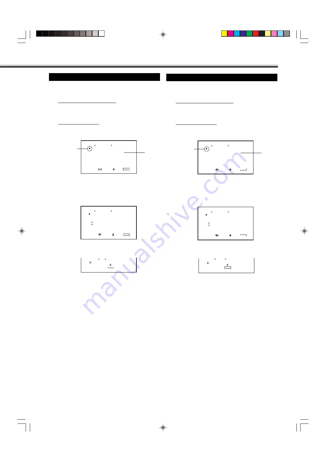
Resetting All the Menu Settings

You can reset all the Menu settings and adjustments at a time,
except the use time (HOUR METER).

1

On the remote control:
Press MENU/EXIT while holding
VOLUME – to display the Setup Menu.

On the Monitor:
Press MENU while holding 

2

 to display

the Setup Menu.

2

Press 

5

/

 to move the cursor (

3

) to “all

reset” (on the second page).

• The Setup Menu consists of two pages. If you keep

pressing 

5

/

, you can move to the other page from

the current page.

3

Press 

3

.

The confirmation screen appears.

To cancel the reset,

 press MENU/EXIT (or MENU on

the Monitor).

4

Press 

3

 again to reset all the Menu

settings and adjustments.

The power is turned off,  then turned on again
automatically.

Cursor (

3

)

A r e   y o u   s u r e ?
" Y E S "   t h e n                       k e y .
" N O "


t h e n                       k e y .

M E N U

a l l   r e s e t

Resetting All the Setup Menu Settings

You can reset all the following Setup Menu settings at a time,
except the use time (HOUR METER).

1

On the remote control:
Press MENU/EXIT while holding
VOLUME – to display the Setup Menu.

On the Monitor:
Press MENU while holding 

2

 to display

the Setup Menu.

2

Press 

5

/

 to move the cursor (

3

) to

“reset” (on the second page).

• The Setup Menu consists of two pages. If you keep

pressing 

5

/

, you can move to the other page from

the current page.

3

Press 

3

.

The confirmation screen appears.

To cancel the reset,

 press MENU/EXIT (or MENU on

the Monitor).

4

Press 

3

 again to reset all the Setup

Menu settings.

Cursor (

3

)

A r e   y o u   s u r e ?
" Y E S "


t h e n                       k e y .

" N O "       t h e n                       k e y .

M E N U

r e s e t

S T A T U S   D I S P L A Y
C O N T R O L   L O C K
R E M O T E   S W I T C H
H D   S I G N A L   M O D E
W H I T E   B A L A N C E
T I M E R

S E T - U P   M E N U           1 / 2

A D J U S T :

S E L E C T :

E X I T : M E N U

:  

O F F

:  

O F F

:   M O D E 1
:   1 0 8 0 i

P I X E L   S H I F T
P O W E R   S A V E
C O L O R - R E V E R S E
R E F R E S H
      r e s e t
      a l l   r e s e t
H O U R   M E T E R   x 1 0 0 h

S E T - U P   M E N U           2 / 2

A D J U S T :

S E L E C T :

E X I T : M E N U

:   O F F
:   O F F

:   1 2 3

*

1

*

1

24-33_VM-4200.p65

03.7.23, 9:30 AM

33

Summary of Contents for VM-4200

Page 1: ...INSTRUCTIONS VM 4200 PLASMA DISPLAY MONITOR LCT1499 001A MENU INPUT Cover p65 03 7 23 9 29 AM 1 ...

Page 2: ...Cover p65 03 7 23 9 29 AM 2 ...

Page 3: ...Signals 10 Connection Diagrams 11 Basic Operations 14 Daily Operations 14 Changing the Aspect Ratio 15 Video Adjustments 16 Adjusting the Picture Quality 16 Adjusting the Screen Size and Position 17 Adjusting the Color Temperature 19 Adjusting the White Balance 19 Changing the Aspect Ratio 21 Setting the Receivable Signal Types 21 Setting the COMPONENT RGB B Input 22 Changing the Resistance of the...

Page 4: ...therefore cause damage to the product Do not use attachments not recommended by the product manufacturer as they may be hazardous Do not use this product near water Do not use immediately after moving from a low temperature to high temperature as this causes condensation which may result in fire electric shock or other hazards Do not place this product on an unstable cart stand or table The produc...

Page 5: ...en require extensive work by a qualified technician to restore the product to normal operation e If the product has been dropped or damaged in any way f When the product exhibits a distinct change in performance this indicates a need for service When replacement parts are required be sure the service technician has used replacement parts specified by the manufacturer or with same characteristics a...

Page 6: ...ion window 3 POWER ON OFF button page 14 Use this button to turn on off the Monitor 4 DISPLAY button page 14 Use this button to display the input terminal color system for VIDEO A or VIDEO B input scan system for COMPONENT input and horizontal vertical frequency for RGB A and RGB B input Pressing the button again will make the display disappear 5 INPUT SELECT VIDEO A VIDEO B COMPO RGB B and RGB A ...

Page 7: ...e level 4 MENU button Use this button to display or erase menus While a sub menu is displayed pressing this button will move you one screen back to the preceding menu 5 INPUT button page 14 Use this button to switch between inputs To select the COMPONENT or RGB B input you have to set RGB COMPO correctly on the menu see page 22 Only RGB A input can be used without the video input unit To reproduce...

Page 8: ...ority over those through the other terminals 3 AUDIO OUT terminals pin jack page 11 Connect to the audio input terminals of external equipment such as an amplifier 4 AC IN terminal page 11 Connect the supplied power cord to this terminal 5 POWER switch page 14 Setting this switch to on will put the Monitor into standby mode allowing you to turn on and off the power using the POWER or button either...

Page 9: ...als page 12 AUDIO L MONO R input terminals pin jack Connect these terminals to the audio output terminals of the other equipment G B R HD Cs VD VIDEO input terminals BNC Connect these terminals to the following output terminals of a personal computer or other equipment Analog RGB signal output terminals Horizontal sync HD signal or composite Cs signal output terminal Vertical sync VD signal output...

Page 10: ...s according to the ª and markings indicated on the battery compartment When installing the batteries insert the end first to avoid a short circuit Use only the specified batteries When you are not using the remote control for a long time remove the batteries When the batteries have reached the end of their life replace them with new ones immediately Otherwise the liquid may leak out or malfunction...

Page 11: ...ontinuously displayed on the screen for a long time otherwise the area on the screen corresponding to the image may vary in brightness leaving an afterimage on the screen To reduce the afterimage you can use the Refresh function see page 31 The Monitor is manufactured using very high precision technology allowing for more than 99 99 active pixels however be aware that only a slight number of pixel...

Page 12: ... 0 66 7 Non interlace 8 SVGA 56 800 600 35 2 56 3 Non interlace 9 SVGA 60 800 600 37 9 60 3 Non interlace 10 SVGA 72 800 600 48 1 72 2 Non interlace 11 SVGA 75 800 600 46 9 75 0 Non interlace 12 XGA 60 1024 768 48 4 60 0 Non interlace 13 XGA 70 1024 768 56 5 70 1 Non interlace 14 XGA 75 1024 768 60 0 75 0 Non interlace 15 XGA 85 1024 768 68 7 85 0 Non interlace 16 XGA 75 1152 864 67 5 75 0 Non int...

Page 13: ... Ex TS C421SPG Power cord supplied To a wall outlet For connection see page 13 To speaker input terminals To speaker input terminals Note It is recommended to use the speaker unit TS C421SPG not supplied as the external speakers You can also connect any speakers of the following specifications Impedance Between 6 Ω and 8 Ω Power handling capacity More than 3 W Caution Do not short circuit the 9 an...

Page 14: ... computer used as the playback source Notes You can connect another VCR or Monitor to the VIDEO A OUT terminal However when connecting a VCR to the VIDEO A terminals do not connect both IN and OUT terminals to the same VCR When connecting a VCR to the VIDEO B terminals you can use either the video or S video terminals If the both terminals are used S video terminal will have priority When connecti...

Page 15: ...e MAKE terminal remote control through the external control unit is automatically activated When the other REMOTE terminals are used at the same time transmitted commands through the MAKE terminal have priority over those through the other terminals IMPORTANT External control unit is not commercially available in the market When you need it consult your dealer MAKE terminal External control unit P...

Page 16: ...g correctly 4 Adjust the volume Note While no menu is displayed you can adjust the volume by pressing 2 3 on the Monitor To turn off the volume immediately Press MUTING MUTING ON is displayed and the sound goes out Pressing the button again resumes the previous volume level To make the screen indication appear Press DISPLAY The types of input and signal are indicated on the screen for about 3 seco...

Page 17: ...grams using a wide screen mode for a while will reduce the burn in gradually With this Monitor you can select among three types of wide screens FULL ZOOM and PANORAMIC in addition to the REGULAR screen of conventional 4 3 aspect ratio Press ASPECT to select the screen size Each time you press the button the screen size changes as follows REGULAR Displays at conventional 4 3 aspect ratio FULL REGUL...

Page 18: ...ss 20 to 20 0 CHROMA 1 20 to 20 0 PHASE 2 20 to 20 0 SHARPNESS 10 to 10 0 sub menu See To make an adjustment while viewing the adjustment bar on the next page reset See To reset the adjustments on the next page 1 Adjustable when viewing the NTSC PAL or SECAM signal or component signal 2 Adjustable when viewing the NTSC signal or component signals 5 Press 2 3 to make adjustments 6 Press MENU EXIT o...

Page 19: ...d proportionally but can be enlarged rightward or downward only and reduced leftward or upward only Therefore it is necessary to adjust both the size and position alternately to adjust to the appropriate size 1 Press MENU EXIT or MENU on the Monitor to display the Main Menu 2 Press 5 to move the cursor 3 to SIZE POSITION ADJ To make an adjustment while viewing the adjustment bar After step 3 on pa...

Page 20: ...er step 3 on page 17 proceed as follows 1 Press 5 to move the cursor 3 to reset 2 Press 3 The confirmation screen appears 3 Press 3 again to reset the adjustments To cancel the reset press MENU EXIT or MENU on the Monitor Note Adjustment values for both horizontal and vertical sizes of the screen are so related that if one is adjusted up to near the maximum value the attainable value of the other ...

Page 21: ...move to the other page from the current page 3 Press 3 to display the White Balance Adjustment Menu 4 Press 5 to move the cursor 3 to the item you want to adjust 5 Press 2 3 to adjust the selected item 6 Repeat steps 4 and 5 to adjust the other items 7 Press MENU EXIT or MENU on the Monitor twice to exit from the menu operations Notes Adjustable range will vary among the Monitors MAX may appear so...

Page 22: ...justments After step 3 on page 19 proceed as follows 1 Press 5 to move the cursor 3 to reset 2 Press 3 The confirmation screen appears 3 Press 3 again to reset the adjustments To cancel the reset press MENU EXIT or MENU on the Monitor 000 R GAIN A r e y o u s u r e Y E S t h e n k e y N O t h e n k e y M E N U r e s e t R GAIN G GAIN B GAIN 2 3 5 5 VIDEO DISPLAY OFF POWER RM C579 REMOTE CONTROL UN...

Page 23: ...r MENU on the Monitor to display the Main Menu 2 Press 5 to move the cursor 3 to FUNCTION SELECT 3 Press 3 to display the Function Selection Menu 4 Press 5 to move the cursor 3 to SIGNAL MODE 5 Press 2 3 to select the receivable video signal type Each time you press the button the receivable video signal type changes as follows When VIDEO A or VIDEO B input is selected When COMPONENT input is sele...

Page 24: ...gnal Each time you press the button the type of signal accepted alternates between RGB and COMPO RGB When connecting the playback device such as a PC which can emit the RGB signals COMPO When connecting the playback device such as a DVD player which can emit the component signals 6 Press MENU EXIT or MENU on the Monitor twice to exit the menu operations PICTURE ADJ SIZE POSITION ADJ FUNCTION SELEC...

Page 25: ... P I C T U R E A D J S I Z E P O S I T I O N A D J F U N C T I O N S E L E C T S T A T U S D I S P L A Y E N T E R M A I N M E N U S E L E C T E X I T M E N U Resetting the Function Selection Menu Settings You can reset all the Function Selection Menu settings at a time 1 Press MENU EXIT or MENU on the Monitor to display the Main Menu 2 Press 5 to move the cursor 3 to FUNCTION SELECT 3 Press 3 to ...

Page 26: ...emote control See page 14 1 Press MENU or MENU EXIT on the remote control to display the Main Menu 2 Press 5 to move the cursor 3 to STATUS DISPLAY 3 Press 3 to display the current input terminal and received signal type Note If you want to make these information appear automatically when you change the input mode see Showing the On screen When Changing the Input Mode on page 25 Input selected PIC...

Page 27: ...remote control Press MENU EXIT while holding VOLUME to display the Setup Menu On the Monitor Press MENU while holding 2 to display the Setup Menu 2 Keep pressing 5 until the second page of the Setup Menu appears The Setup Menu consists of two pages If you keep pressing 5 you can move to the other page from the current page 3 Confirm the hour of use The displayed value for the hours of use is divid...

Page 28: ...alternates between ON and OFF To cancel the Control Lock function select OFF 4 Press MENU EXIT or MENU on the Monitor once to exit from the menu operations Note Even when the Control Lock function is in use the following operations are possible Operation to cancel the Control Lock function All operations from the remote control Cursor 3 STATUS DISPLAY CONTROL LOCK REMOTE SWITCH HD SIGNAL MODE WHIT...

Page 29: ... while holding VOLUME to display the Setup Menu On the Monitor Press MENU while holding 2 to display the Setup Menu 2 Press 5 to move the cursor 3 to REMOTE SWITCH The Setup Menu consists of two pages If you keep pressing 5 you can move to the other page from the current page 3 Press 2 3 to select the desired setting Each time you press the button the Remote Switch Mode changes as follows MODE1 In...

Page 30: ...er page from the current page 3 Press 5 to move the cursor 3 to PRESENT TIME then press 3 4 Press 5 to move the cursor 3 to HOURS then press 2 3 repeatedly to adjust the hour 24 hour clock 5 Press 5 to move the cursor 3 to MINUTES then press 2 3 repeatedly to adjust the minute 6 Press MENU EXIT or MENU on the Monitor three times to exit from the menu operations Cursor 3 STATUS DISPLAY CONTROL LOCK...

Page 31: ...lect OFF 4 Press MENU EXIT or MENU on the Monitor once to exit from the menu operations Using the Power Save Function You can use this function to reduce the electrical consumption and to extend the lifetime of the Monitor s screen The brightness of the screen will be reduced 1 On the remote control Press MENU EXIT while holding VOLUME to display the Setup Menu On the Monitor Press MENU while hold...

Page 32: ...enu operations OFF The function is deactivated TIMER Select this when you use the Color Reverse On Off Timer Note Set the clock see page 28 and select TIMER before using the Color Reverse On Off Timer START SET You can activate deactivate the Color Reverse On Timer Press 2 3 to select ON or OFF ON The function is automatically activated at the time set in START TIME OFF The Color Reverse On Timer ...

Page 33: ... P M E N U 1 2 A D J U S T S E L E C T E X I T M E N U O F F O F F M O D E 1 1 0 8 0 i Cursor 3 P I X E L S H I F T P O W E R S A V E C O L O R R E V E R S E R E F R E S H r e s e t a l l r e s e t H O U R M E T E R x 1 0 0 h S E T U P M E N U 2 2 A D J U S T S E L E C T E X I T M E N U O F F O F F 1 2 3 3 Press 5 to select the item you want to set and set the item as follows REFRESH You can activ...

Page 34: ...R O N S E T P O W E R O N T I M E P O W E R O F F S E T P O W E R O F F T I M E r e s e t T I M E R A D J U S T S E L E C T E X I T M E N U 1 4 2 5 O N 0 8 2 6 O N 2 1 2 0 B A T T E R Y L O W PRESENT TIME POWER ON SET POWER ON TIME POWER OFF SET POWER OFF TIME reset TIMER ADJUST SELECT EXIT MENU OFF OFF BATTERY EMPTY 1 REMOTE SWITCH does not appear on the menu unless the video input unit IF C42P1G...

Page 35: ...he Setup Menu 2 Press 5 to move the cursor 3 to reset on the second page The Setup Menu consists of two pages If you keep pressing 5 you can move to the other page from the current page 3 Press 3 The confirmation screen appears To cancel the reset press MENU EXIT or MENU on the Monitor 4 Press 3 again to reset all the Setup Menu settings Cursor 3 A r e y o u s u r e Y E S t h e n k e y N O t h e n...

Page 36: ... 0 1 H S I Z E 0 1 H P O S I T I O N 0 1 V S I Z E 0 1 V P O S I T I O N 0 1 D O T C L O C K A r e y o u s u r e Y E S N O M E N U r e s e t t h e n t h e n k e y k e y A r e y o u s u r e Y E S N O M E N U r e s e t t h e n t h e n k e y k e y A r e y o u s u r e Y E S N O M E N U r e s e t t h e n t h e n k e y k e y 0 0 0 1 C L O C K P H A S E Menu Classifications Main Menu 1 Adjustable when vi...

Page 37: ... pages 19 to 23 COLOR TEMP Adjusts the color temperature Use when the picture is reddish or bluish ASPECT 4 Selects the horizontal to vertical ratio of the screen SIGNAL MODE 5 Selects a color system NTSC PAL SECAM NTSC 4 43 PAL60 when VIDEO A or VIDEO B input is selected Selects a scan system 480i 576i 480p 720p 1080i 1035i when COMPONENT input is selected Normally set to AUTO RGB COMPO 6 Selects...

Page 38: ... O R R E V E R S E S T A R T S E T S T A R T T I M E E N D S E T E N D T I M E r e s e t C O L O R R E V E R S E C O L O R R E V E R S E C O L O R R E V E R S E A D J U S T S E L E C T E X I T M E N U O F F O N 0 8 0 6 O N 2 1 4 7 P R E S E N T T I M E H O U R S M I N U T E S 1 4 2 5 1 4 2 5 T I M E R P O W E R O N T I M E H O U R S M I N U T E S 0 8 2 6 0 8 2 6 T I M E R P O W E R O F F T I M E H...

Page 39: ... GAIN and B GAIN finely each for HIGH and LOW settings of the color temperature See page 19 TIMER Sets the clock and the Power On Off Timer See page 28 PIXEL SHIFT Sets a screen saver See page 29 POWER SAVE Sets the power save function See page 29 COLOR REVERSE Use to reverse the color of the still picture to prevent its afterimage from being left on the screen See page 30 REFRESH Use to eliminate...

Page 40: ...oo far away from you Is the Control Lock function in use 11 14 28 14 11 12 22 10 16 14 39 17 23 16 16 39 21 10 30 31 17 8 8 26 Troubleshooting Solutions to common problems related to the Monitor are described here If none of the solutions presented here solves the problem unplug the Monitor and consult an authorized dealer or service center Symptom Probable cause Corrective action Page Insert the ...

Page 41: ...improper installation or improper location of the Monitor In this case consult your dealer immediately to solve this improper installation and to improve the circumstances around the Monitor If TEMP OVER lights in red TEMP OVER will be shown for abut two minutes the Monitor will shut off automatically then the Self diagonal lamps light in red If this happens switch off the main power by POWER swit...

Page 42: ... terminal x 1 Y 1 V p p 75 Ω C 0 286 V p p 75 Ω for NTSC C 0 3 V p p 75 Ω for PAL SECAM Video input Pin jack terminal x 1 1 V p p 75 Ω Audio input Pin jack terminal x 2 L R 500 mV rms high impedance General Input output terminals 1 1 This monitor does not have the following input terminals VIDEO A VIDEO B and COMPONENT RGB B You need to install the video input unit IF C42P1G which is separately pu...

Page 43: ...sitive negative polarity Vertical sync VD VD 1 V p p to 5 V p p 470 Ω positive negative polarity Audio input Stereo mini jack terminal x 1 500 mV rms high impedance REMOTE terminals RS 232C D sub 9 pin terminal x 1 MAKE Mini DIN 4 pin WIRED Stereo mini jack terminal x 1 OPTION terminal Used exclusively for JVC s optional parts AUDIO OUT terminals Pin jack terminal x 2 L R Output impedance 600 Ω SP...

Page 44: ...sions Pin number Signal name 1 Red 2 Green 3 Blue 4 N C 5 GND 6 GND 7 GND 8 GND Pin number Signal name 9 N C 10 GND 11 GND 12 N C 13 HD Cs 14 VD 15 N C External GND Pin number Signal name 1 GND 2 GND 3 SW2 4 SW1 5 SW DET 6 GND MAKE terminal RGB Input Terminal 1 2 8 4 5 6 7 3 9 10 11 12 13 14 15 1 2 3 4 6 5 1 2 3 4 Unit mm VM 4200 PLASMA DISPLAY MONITOR VICTOR COMPANY OF JAPAN LIMITED 2003 VICTOR C...

Reviews: