


RX-E112RSL/RX-E111RSL
1-6
Prior to performing the following procedure, remove
the top cover.
Remove the screw G attaching the power/fuse board
to the rear panel (see fig. 4).
Disconnect the harness from the connector CN217
on the power/fuse board (If necessary, cut off the
band fixing the harness on the side of the base
chassis).
Remove the screw U attaching the power/fuse
board.
Unsolder the power cord and other harness
connected to the power/fuse board.
1.
2.
3.
4.
Removing the power/fuse board
(See Fig.13)
Prior to performing the following procedures, remove
the top cover.
Cut off the tie band.
Disconnect the harness from the connector CN217
on the power/fuse board.
Disconnect the harness from the connector CN201
on the power supply board and CN202 on the main
board.
Remove the one screw J and remove the earth wire.
Remove the four screws R attaching the power
transformer.
1.
2.
3.
4.
5.
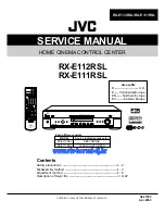
Removing the power transformer
(See Fig.12 and 13)
Prior to performing the following procedure, remove
the top cover.
Disconnect the card wire from the connector CN204
on the power supply board.
Disconnect the harness from the connector CN201,
CN209 and CN707 on the power supply board.
Disconnect the harness from the connector CN226
/CN227 on the main board
Remove the three screws S attaching the power
supply board and pull out the power supply board
removing the hook.
Unsolder the three harness connected to the power
supply board (If necessary, cut off the band fixing the
harness on the side of the base chassis).
1.
2.
3.
4.
5.
Removing the power supply board
(See Fig.12)
Fig.12
Fig.13
Power supply
board
CN707
Power
transformer
Solder
Solder
(on the reverse side)
Solder
Power/fuse board
Power cord
Tie band
Tie band
Power
transformer
board
PW201
PW203
CN204
CN209
PW202
S
S
R
J
(fixing the
earth wire)
S
CN201
U
CN217
Hook
CN226
/CN227
CN202


