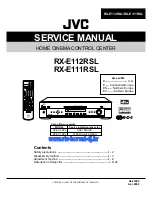


RX-E112RSL/RX-E111RSL
1-12
M61501FP (IC501) : Analog sound processor
1. Block diagram
2. Pin function (1/2)
Pin No.
1
2
3
4
5
6
7
8
9
10
11
12
13
14
15
16
17
18
19
20
21
I/O
-
I
O
O
O
I
I
I
I
I
O
O
-
I
I
O
O
I
-
I
I
Symbol
NC
ING1
RECOUT1B
RECOUT1A
SELOUT1
TINA1
TINB1
TCC
TCB1
TCA1
TONEOUT1
SWOUT
AGND
RchAIN
RchBIN
RchOUT
RchBBO
RchBBI
AGND
SRchAIN
SRchBIN
Function
No connect
G signal input of right side input selector
B through signal output of right side
A through signal output of right side
Signal output after 0/-6dB of right side
Tone A signal input of right side
Tone B signal input of right side
Tone C control of right side
Tone B control of right side
Tone A control of right side
Tone signal output of right side
L+R+C signal output
Analog ground for Rch
A select signal input of Rch
B select signal input of Rch
Signal output of Rch
Bus boost control output of Rch
Bus boost control input of Rch
Analog ground for SRch
A signal input of SRch
B signal input of SRch
40 39 38 37 36 35 34 33 32 31 30 29 28 27 26 25
MCU I/F
B
A
M
B
A
M
B
A
B
A
B
SW2
SW1
A
+
M
Cch Vol
SLch Vol
Lch Vol
BYPASS
TONE
Bus boost
0/6/10dB
0/6/10dB
0/6/10dB
L+R+C
0/-6dB
AT
T
10/2dB
B
A
M
B
A
M
B
A
B
A
B
SW2
SW1
A
M
SWch Vol
SRch Vol
Rch Vol
BYPASS
TONE
Bus boost
0/6/10dB
0/6/10dB
0/6/10dB
0/-6dB
AT
T
10/2dB
65 66 67 68 69 70 71 72 73 74 75 76 77 78 79 80
41
42
43
44
45
46
47
48
49
50
51
52
53
54
55
56
57
58
59
60
61
62
63
64
24
23
22
21
20
19
18
17
16
15
14
13
12
11
10
9
8
7
6
5
4
3
2
1


