background image

17

To obtain the best possible sound effect from Surround/DSP
modes (see pages 29 to 33), you need to set up the speaker and
subwoofer information after all the connections are completed.
From pages 17 to 22, how to set speakers and other basic items
of the receiver are explained.

Setting the speaker information
easily—Quick Speaker Setup

Quick Speaker Setup helps you to easily and quickly register the
speaker size, speaker distance, and output level of each speaker
according to your listening room to create the best possible
surround effect.
• You can also register each speaker’s information manually.

For details, see pages 20 and 24.

Before you start, remember...

There is a time limit in doing the following steps. If the setting is
canceled before you finish, start from step 

1

 again.

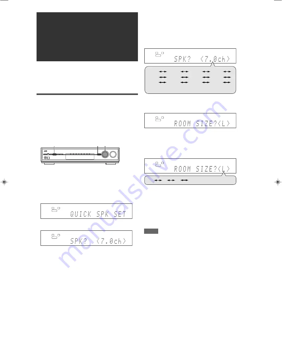
1

Press SETTING and turn MULTI JOG until
"QUICK SPK SET" appears on the display.

2

Press SET.

Basic settings

3

Turn MULTI JOG to select an appropriate
number of the connected speakers (speaker
channel number).

As you turn the jog, the speaker channel number changes as
follows.
• For the details of speaker channel number, see “ Speakers

(channels) number and the size” on page 18.

* “7.0ch” is the initial setting.

4

Press SET.

5

Turn MULTI JOG to select an appropriate
room size to match to your listening room.

As you turn the jog, the room size changes as follows.
• To select your appropriate room size, see “Room size and

the speaker distance/output level” on page 18.

* “L” is the initial setting.

6

Press SET.

QUICK SPEAKER SETUP is now completed, then the display
goes back to SETTING menu.

7

Press SETTING.

NOTES

• This procedure will not be completed if you stop in the middle of

the setting process.

• Once Quick Speaker Setup is performed, the speaker output

levels are also set to appropriate values automatically (common
to all sources). If you want to set the speaker output levels
separately for each source, see “Adjusting the speaker output
levels” on page 24.

L

S.WFR

R

ANALOG

L

S.WFR

R

ANALOG

L

S.WFR

R

ANALOG

CONTINUED ON THE NEXT PAGE

L

S.WFR

R

ANALOG

(Back to the beginning)

S

M

L*

1,7

2,4,6 1,3,5

L

S.WFR

R

ANALOG

3.1ch

4.0ch

6.0ch

6.1ch

4.1ch

2.0ch

2.1ch

5.0ch

5.1ch

7.0ch*

7.1ch

3.0ch

(Back to the beginning)

17-22RX-D301S[J]_f.p65

05.2.22, 16:44

17

Summary of Contents for RX-D301S

Page 1: ...2B AUDIO VIDEO CONTROL RECEIVER INSTRUCTIONS For Customer Use Enter below the Model No and Serial No which are located either on the rear bottom or side of the cabinet Retain this information for future reference Model No Serial No ...

Page 2: ...peration is subject to the following two conditions 1 This device may not cause harmful interference 2 This device must accept any interference received including interference that may cause undesired operation Responsible Party JVC Americas Corp Address 1700 Valley Road Wayne New Jersey 07470 Telephone Number 973 317 5000 For USB wireless transmitter This device complies with Part 15 of the FCC R...

Page 3: ...AL MONO 21 Setting bass sound 21 Using the Midnight mode MIDNIGHT MODE 21 Setting the digital input DIGITAL IN terminals DIGITAL IN 1 2 3 22 Selecting the component video input mode DVD VIDEO IN VCR VIDEO IN DBS VIDEO IN 22 Memorizing the volume level for each source ONE TOUCH OPE 22 Sound adjustments 23 Basic adjustment items 23 Operating procedure 23 Adjusting the speaker output levels 24 Adjust...

Page 4: ... 10 0 10 100 RETURN button 36 a C center TONE button 26 s EFFECT button 25 d DIMMER button 16 f SLEEP button 16 g TEST button 24 These buttons can be used for operating a JVC DVD recorder or DVD player with the mode selector set to DVR or DVD see page 37 If these buttons do not function normally use the remote control supplied with your DVD recorder or DVD player Refer also to the manuals supplied...

Page 5: ... 31 and indicator 29 31 Main display B bass BOOST indicator 25 MIDNIGHT indicator 21 Frequency unit indicators MHz for FM stations kHz for AM stations 9 COMPONENT VIDEO Y PB PR jacks 7 10 VCR DBS IN DVR DVD IN MONITOR OUT p AUDIO jacks 7 10 Input TV IN DBS IN VCR IN PLAY DVR DVD IN PLAY Output VCR OUT REC DVR OUT REC q DVD MULTI IN jacks 8 CENTER SUBWOOFER SURR L SURR R w Speakers terminals 6 SURR...

Page 6: ...e temperature around the receiver must be between 5 C and 35 C 23 F and 95 F Make sure there is good ventilation around the receiver Poor ventilation could cause overheating and damage the receiver Leave sufficient distance between the receiver and the TV Handling the receiver Do not insert any metal object into the receiver Do not disassemble the receiver or remove screws covers or cabinet Do not...

Page 7: ... single vinyl covered wire not supplied to the AM EXT terminal Keep the AM loop antenna connected FM antenna connection Connect the FM antenna supplied to the FM 75 Ω COAXIAL terminal as a temporary measure Extend the supplied FM antenna horizontally If the reception is poor connect an outdoor FM antenna not supplied Before attaching a 75 Ω coaxial cable with a connector disconnect the supplied FM...

Page 8: ...rear panel to the and terminals marked on the speakers 3 Close the terminal When using a single speaker for the surround back speaker You can enjoy the surround sound by one surround back speaker When using one surround back speaker set SB OUT to 1SPK see page 19 and connect the surround back speaker to the left surround back speaker terminal No sound comes from the speaker if you connect it to th...

Page 9: ...ystem cannot operate properly See page 22 for details You can enjoy digital sound if using a digital coaxial or optical cable When shipped from the factory the audio input mode for a DVD recorder and DVD player is set to use the digital coaxial terminal DIGITAL IN 1 DVR DVD For details of digital connection see page 11 Turn off all components before making connections When you connect other compon...

Page 10: ...To component video output Connect Y PB and PR correctly Î To subwoofer output To left right front channel audio output Ï Only for DVD recorder To left right front channel audio input Ì To composite video output Ó To S video output È Only for DVD recorder To S video input Ô Only for DVD recorder To composite video input NOTE When connecting a DVD recorder or DVD player to the component video input ...

Page 11: ...ecting a VCR to the component video input jacks select the component video input mode VCR VIDEO IN correctly If you do not you cannot view the playback picture on the TV or the AV COMPU LINK remote control system cannot operate properly See page 22 for details You can enjoy digital sound if using a digital coaxial or optical cable When shipped from the factory the audio input mode for a VCR is set...

Page 12: ...reen Blue Component video cable not supplied Å To left right audio channel output ı To component video output Connect Y PB and PR correctly Ç To composite video output Î To S video output NOTE You can enjoy digital sound if using a digital coaxial or optical cable For details of digital connection see page 11 NOTES When connecting a DBS tuner to the component video input jacks select the component...

Page 13: ...utput terminal connect it to the 2 DBS or 3 VCR terminal using a digital optical cable not supplied Before connecting a digital optical cable unplug the protective plug NOTE The digital signal format transmitted through the DIGITAL OUT terminal is the same as that of the input signal For example when the DTS signals are input the DTS signals are transmitted 7 Digital output terminal You can connec...

Page 14: ...equipped with a USB terminal on the front panel and a USB WIRELESS ANTENNA terminal on the rear You can enjoy sound reproduced through your PC with either of the following methods 1 connecting a USB wireless antenna supplied to the USB WIRELESS ANTENNA terminal and a USB wireless transmitter supplied to your PC USB WIRELESS 2 connecting your PC to the USB terminal with a USB cable not supplied USB...

Page 15: ...patible with the USB device open the Control Panel on your PC select Sounds and Audio Devices Audio tab Sound playback Default device and check Default device is set to USB Audio device For USB WIRELESS select USB WIRELESS as the source connect the USB wireless transmitter correctly with the USB WIRELESS switch on the receiver ON keep proper distance between the receiver and your PC check the ID l...

Page 16: ...te control ONLY Press ANALOG DIGITAL to select the analog or digital input mode Each time you press the button the input mode alternates between the analog input ANALOG and the digital input DGTL AUTO This setting is memorized for each source DGTL AUTO DIGITAL AUTO Select for the digital input mode The receiver automatically detects the incoming signal format then the digital signal format indicat...

Page 17: ...splay and the volume turns off To restore the sound press MUTING again Pressing VOLUME or turning MASTER VOLUME control on the front panel also restores the sound 3 Adjust the volume To increase the volume turn MASTER VOLUME control clockwise or press VOLUME on the remote control To decrease the volume turn MASTER VOLUME control counterclockwise or press VOLUME on the remote control When you adjus...

Page 18: ...than DIMMER 1 DIMMER 3 Turns off the display Temporarily canceled when you operate the receiver DIMMER OFF Cancels the Dimmer normal display Turning off the power with the Sleep Timer You can fall asleep while listening to music Sleep Timer From the remote control ONLY Press SLEEP repeatedly Each time you press the button the shut off time changes in 10 minute intervals The SLEEP indicator lights ...

Page 19: ...mber As you turn the jog the speaker channel number changes as follows For the details of speaker channel number see Speakers channels number and the size on page 18 7 0ch is the initial setting 4 Press SET 5 Turn MULTI JOG to select an appropriate room size to match to your listening room As you turn the jog the room size changes as follows To select your appropriate room size see Room size and t...

Page 20: ...T SPK Register your front speaker size 19 CENTER SPK Register your center speaker size 19 SURROUND SPK Register your surround speaker size 19 S BACK SPK Register your surround back speaker size 19 S BACK OUT Register the number of your surround back speaker s 19 DIST UNIT Select the measuring unit for the speaker distance 20 FRONT L DIST Register the distance from the left front speaker to your li...

Page 21: ...s of all the connected speakers LRG large Select when the cone speaker size is larger than 12 cm 4 3 4 inches SML small Select when the cone speaker size is smaller than 12 cm 4 3 4 inches NO Select when you have disconnected a speaker Not selectable for the front speakers Initial setting LRG for the front speakers SML for other speakers Setting the surround back speaker s S BACK OUT Register the ...

Page 22: ...t for all speakers Activating the EX ES PLIIx setting EX ES PLIIx Depending on this setting available Surround modes for digital multi channel software vary EX ES PLIIx 7 1 channel reproduction or 5 1 channel reproduction Select an appropriate setting for your enjoyment For details about relation between EX ES PLIIx setting and available Surround mode see page 32 To activate the Surround mode see ...

Page 23: ...ments of the front speakers channels MAIN when no bass elements are emitted through the subwoofer in SW LFE Initial setting SW LFE NOTE When SUBWOOFER is set to SUBWFR NO see page 19 this function is not available The LFE signals are emitted only when playing the following software with the LFE signals Dolby Digital multi channel software DTS multi channel software When playing analog source or li...

Page 24: ...r DVD VIDEO IN DVD S C Select when connecting the DVD recorder or DVD player to the composite video or S video input jacks DVD CMPNT Select when connecting the DVD recorder or DVD player to the component video input jacks Initial setting DVD S C For the VCR VCR VIDEO IN VCR S C Select when connecting the VCR to the composite video or S video input jacks VCR CMPNT Select when connecting the VCR to ...

Page 25: ...ter channel localization between the center speaker and the left right speakers 26 DIMENSION Adjust sound localization pattern 26 CENTER GAIN Adjust the sound localization of the center channel 26 CENTER TONE 1 Make the center tone soft or sharp 26 CENTER ALIGN Align the vertical localization of the center channel signals 26 1 You can also use the remote control for the adjustment 2 If you have us...

Page 26: ...VL right surround back speaker output level You can adjust the speaker output levels Adjust all the speakers output levels so that you can listen to the sounds from all the speakers at the same level Once you have made an adjustment it is memorized for each source Adjustable range 10 dB to 10 dB in 1 step intervals Initial setting 0 dB for all speakers NOTES If you have selected NO for a speaker s...

Page 27: ...ontrol Press EFFECT to select the level you want to adjust Adjusting the virtual room size for DSP modes ROOM SIZE This setting is available only when one of the DSP modes except ALL CH STEREO is in use To activate DSP mode see page 33 If SURROUND SPK is set to NO see page 19 this item is not adjustable Once you have made an adjustment it is memorized for each DSP mode You cannot use the remote co...

Page 28: ...is set to NO see page 19 this item is not adjustable Once you have made an adjustment it is memorized until you change the setting You cannot use the remote control for this setting Adjustable range 0 to 1 0 in 0 1 step intervals Initial setting C GAIN 0 3 As the number increases the center channel will be localized clearly Normally select 0 3 Adjusting the center tone CENTER TONE This setting is ...

Page 29: ...et stations Before you start remember There is a time limit in doing the following steps If the setting is canceled before you finish start from step 2 again From the remote control ONLY 1 Tune in to the station you want to preset see Tuning in to stations manually above If you want to store the FM reception mode for this station select the FM reception mode you want See Selecting the FM reception...

Page 30: ...d station of the selected band is tuned in 2 Press TUNER PRESET P appears on the display and MULTI JOG now works for selecting preset channels 3 Turn MULTI JOG to select a preset channel number To increase the preset channel numbers turn MULTI JOG clockwise To decrease the preset channel numbers turn MULTI JOG counterclockwise Selecting the FM reception mode When an FM stereo broadcast is hard to ...

Page 31: ...g there feeling are enhanced much more than Dolby Pro Logic Dolby Digital EX Dolby Digital EX DOLBY D EX is a digital surround encoding format that adds the third surround channels called surround back Compared to the conventional Dolby Digital 5 1CH these newly added surround back channels can reproduce more detailed movements behind you while viewing the video software In addition surround sound...

Page 32: ...annel software but 2 channel software into 7 1 channel or 6 1 channel that developed from Dolby Pro Logic II The matrix based conversion method used for Dolby Pro Logic IIx makes no limitation for the cutoff frequency of the surround treble This receiver provides two types of Dolby Pro Logic IIx modes Pro Logic IIx Movie PLIIx MOVIE and Pro Logic IIx Music PLIIx MUSIC When Dolby Pro Logic IIx is a...

Page 33: ...ER2 Reproduces the spatial feeling of a small theater where the seating capacity is about 300 NOTE When THEATER1 or THEATER2 is activated while playing back 2 channel analog or digital source the built in Dolby Pro Logic II decoder is activated and the indicator lights up Early reflections Direct sounds Reflections from behind When using the DAP mode the sounds come out of all the connected and ac...

Page 34: ... is activated If you want to apply the processing set the EX ES PLIIx setting to OFF see page 20 2 When S BACK OUT is set to 1SPK D PLIIx MOVIE is changed to DOLBY D EX and DTS PLIIx MOVIE is changed to DTS EX 3 When S BACK SPK is set to NO Virtual Surround Back is activated for the modes and the VIRTUAL SB indicator lights up on the display 4 When S BACK SPK is set to NO PLllx MOVIE is changed to...

Page 35: ...ngs and the incoming signals For details see page 32 Activating one of the Surround DSP modes automatically recalls the memorized settings and adjustments To adjust the speaker output level see page 24 When activating one of the Surround DSP modes you can adjust CENTER TONE see page 26 When activating one of the Surround DSP modes except Pro Logic IIx Music Pro Logic II Music NEO 6 Music and ALL C...

Page 36: ...s receiver will not be selected on the TV To video input 1 S video cable S video cable VCR DVD player TV Monaural mini plugs not supplied Case 1 When connecting the source equipment to the receiver through the S video terminals connect this receiver to the TV s video input 1 terminal using S video cables Monaural mini plugs not supplied IMPORTANT The AV COMPU LINK remote control system cannot cont...

Page 37: ... When you turn off the receiver the TV DVD player and VCR will turn off NOTE If you turn off the receiver while recording on the VCR the VCR will not turn off but continue recording Connecting procedure 1 If you have already plugged your VCR DVD player TV and this receiver into the AC outlets unplug their AC power cords first 2 Connect your VCR DVD player TV and this receiver as follows using the ...

Page 38: ...oducts You can always perform the following operations TV Turn on or off the TV TV VOL Adjust the volume on the TV TV VIDEO Change the input mode either video input or TV tuner on the TV After pressing TV you can perform the following operations on the TV CHANNEL Change the channel numbers 1 9 0 100 10 Select the channel numbers RETURN 10 Switch between the previous channel and the current channel...

Page 39: ...em etc If these buttons do not function normally use the remote control supplied with your DVD recorder or DVD player Refer also to the manuals supplied with the DVD recorder or DVD player for details After setting the mode selector correctly you can perform the following operations on the DVD recorder or DVD player See the instructions supplied with the DVD recorder or DVD player for details 7 Ch...

Page 40: ...either TV or VIDEO After pressing TV you can perform the following operations on the TV CHANNEL Change the channel numbers 1 9 0 100 10 Select the channel numbers See the instructions supplied with the TV for details 5 Try to operate your TV by pressing TV When your TV turns on or off you have entered the correct code If more than one code is listed for your brand of TV try each one until the corr...

Page 41: ...s supplied with the VCR for details 5 Try to operate your VCR by pressing VCR When your VCR turns on or off you have entered the correct code If more than one code is listed for your brand of VCR try each one until the correct one is entered Manufacturers codes for VCR Manufacturers codes are subject to change without notice If they are changed this remote control cannot operate the equipment Manu...

Page 42: ...ils 5 Try to operate your CATV converter or DBS tuner by pressing DBS CATV When your CATV converter or DBS tuner turns on or off you have entered the correct code If more than one code is listed for your brand of CATV converter or DBS tuner try each one until the correct one is entered Changing the transmittable signals for operating a DVD player 1 Set the mode selector to DVD 2 Press and hold DVR...

Page 43: ...obstruction hiding the remote sensor on the receiver Batteries are weak The mode selector is set to the incorrect position Incoming signal is too weak The station is too far away The wrong antenna is being used Antennas are not connected properly Ignition noise from automobiles SOLUTION Plug the power cord into an AC outlet 1 Stop the playback source 2 Turn on the receiver again then turn the volu...

Page 44: ...quency Response 6 Ω 20 Hz to 20 kHz 1 dB Bass Boost 4 dB 1 dB at 100 Hz Equalization at DSP operation Center frequency 63 Hz 250 Hz 1 kHz 4 kHz 16 kHz Control range 8 dB Specifications Video Video Input Sensitivity Impedance Composite video DVR DVD VCR DBS 1 V p p 75 Ω S video DVR DVD VCR DBS Y luminance 1 V p p 75 Ω C chrominance burst 0 286 V p p 75 Ω Component DVR DVD VCR DBS Y luminance 1 V p ...

Page 45: ......

Page 46: ......

Page 47: ...0205RYMMDWJEIN EN 2005 Victor Company of Japan Limited AUDIO VIDEO CONTROL RECEIVER RX D301S RX D302B ...

Page 48: ...English Français LVT1321 002A C RX D302B AUDIO VIDEO CONTROL RECEIVER RECEPTURE DE COMMANDE AUDIO VIDEO INSTRUCTIONS MANUEL D INSTRUCTIONS ...

Page 49: ...ion is subject to the following two conditions 1 This device may not cause harmful interference 2 This device must accept any interference received including interference that may cause undesired operation Responsible Party JVC Americas Corp Address 1700 Valley Road Wayne New Jersey 07470 Telephone Number 973 317 5000 For USB wireless transmitter This device complies with Part 15 of the FCC Rules ...

Page 50: ...l DUAL MONO 21 Setting bass sound 21 Using the Midnight mode MIDNIGHT MODE 21 Setting the digital input DIGITAL IN terminals DIGITAL IN 1 2 3 22 Selecting the component video input mode DVD VIDEO IN VCR VIDEO IN DBS VIDEO IN 22 Memorizing the volume level for each source ONE TOUCH OPE 22 Sound adjustments 23 Basic adjustment items 23 Operating procedure 23 Adjusting the speaker output levels 24 Ad...

Page 51: ...40 1 10 0 10 100 RETURN button 36 a C center TONE button 26 s EFFECT button 25 d DIMMER button 16 f SLEEP button 16 g TEST button 24 These buttons can be used for operating a JVC DVD recorder or DVD player with the mode selector set to DVR or DVD see page 37 If these buttons do not function normally use the remote control supplied with your DVD recorder or DVD player Refer also to the manuals supp...

Page 52: ...r 30 31 and indicator 29 31 Main display B bass BOOST indicator 25 MIDNIGHT indicator 21 Frequency unit indicators MHz for FM stations kHz for AM stations 9 COMPONENT VIDEO Y PB PR jacks 7 10 VCR DBS IN DVR DVD IN MONITOR OUT p AUDIO jacks 7 10 Input TV IN DBS IN VCR IN PLAY DVR DVD IN PLAY Output VCR OUT REC DVR OUT REC q DVD MULTI IN jacks 8 CENTER SUBWOOFER SURR L SURR R w Speakers terminals 6 ...

Page 53: ...and dust The temperature around the receiver must be between 5 C and 35 C Make sure there is good ventilation around the receiver Poor ventilation could cause overheating and damage the receiver Leave sufficient distance between the receiver and the TV Handling the receiver Do not insert any metal object into the receiver Do not disassemble the receiver or remove screws covers or cabinet Do not ex...

Page 54: ...door single vinyl covered wire not supplied to the AM EXT terminal Keep the AM loop antenna connected FM antenna connection Connect the FM antenna supplied to the FM 75 Ω COAXIAL terminal as a temporary measure Extend the supplied FM antenna horizontally If the reception is poor connect an outdoor FM antenna not supplied Before attaching a 75 Ω coaxial cable with a connector disconnect the supplie...

Page 55: ...the rear panel to the and terminals marked on the speakers 3 Close the terminal When using a single speaker for the surround back speaker You can enjoy the surround sound by one surround back speaker When using one surround back speaker set SB OUT to 1SPK see page 19 and connect the surround back speaker to the left surround back speaker terminal No sound comes from the speaker if you connect it t...

Page 56: ... on the TV or the AV COMPU LINK remote control system cannot operate properly See page 22 for details You can enjoy digital sound if using a digital coaxial or optical cable When shipped from the factory the audio input mode for a DVD recorder and DVD player is set to use the digital coaxial terminal DIGITAL IN 1 DVR DVD For details of digital connection see page 11 Turn off all components before ...

Page 57: ...t Ç To component video output Connect Y PB and PR correctly Î To subwoofer output To left right front channel audio output Ï Only for DVD recorder To left right front channel audio input Ì To composite video output Ó To S video output È Only for DVD recorder To S video input Ô Only for DVD recorder To composite video input NOTE When connecting a DVD recorder or DVD player to the component video in...

Page 58: ...nalog or digital input mode on page 14 When connecting a VCR to the component video input jacks select the component video input mode VCR VIDEO IN correctly If you do not you cannot view the playback picture on the TV or the AV COMPU LINK remote control system cannot operate properly See page 22 for details You can enjoy digital sound if using a digital coaxial or optical cable When shipped from t...

Page 59: ...To component video output Connect Y PB and PR correctly Ç To composite video output Î To S video output NOTES Select the analog input mode See Selecting the analog or digital input mode on page 14 You can enjoy digital sound if using a digital coaxial or optical cable For details of digital connection see page 11 NOTES Select the analog input mode See Selecting the analog or digital input mode on ...

Page 60: ...al output terminal connect it to the 2 DBS or 3 VCR terminal using a digital optical cable not supplied Before connecting a digital optical cable unplug the protective plug NOTE The digital signal format transmitted through the DIGITAL OUT terminal is the same as that of the input signal For example when the DTS signals are input the DTS signals are transmitted 7 Digital output terminal You can co...

Page 61: ...h a USB terminal on the front panel and a USB WIRELESS ANTENNA terminal on the rear You can enjoy sound reproduced through your PC with either of the following methods 1 connecting a USB wireless antenna supplied to the USB WIRELESS ANTENNA terminal and a USB wireless transmitter supplied to your PC USB WIRELESS 2 connecting your PC to the USB terminal with a USB cable not supplied USB TERMINAL Wh...

Page 62: ... compatible with the USB device open the Control Panel on your PC select Sounds and Audio Devices Audio tab Sound playback Default device and check Default device is set to USB Audio device For USB WIRELESS select USB WIRELESS as the source connect the USB wireless transmitter correctly with the USB WIRELESS switch on the receiver ON keep proper distance between the receiver and your PC check the ...

Page 63: ... DIGITAL to select the analog or digital input mode Each time you press the button the input mode alternates between the analog input ANALOG and the digital input DGTL AUTO This setting is memorized for each source DGTL AUTO DIGITAL AUTO Select for the digital input mode The receiver automatically detects the incoming signal format then the digital signal format indicator LINEAR PCM or 96 24 for t...

Page 64: ...e display and the volume turns off To restore the sound press MUTING again Pressing VOLUME or turning MASTER VOLUME control on the front panel also restores the sound 3 Adjust the volume To increase the volume turn MASTER VOLUME control clockwise or press VOLUME on the remote control To decrease the volume turn MASTER VOLUME control counterclockwise or press VOLUME on the remote control When you a...

Page 65: ...s the source this function is not available Changing the display brightness You can dim the display Dimmer From the remote control ONLY Press DIMMER repeatedly Each time you press the button the display brightness changes as follows DIMMER 1 Dims the display DIMMER 2 Dims the display more than DIMMER 1 DIMMER 3 Turns off the display Temporarily canceled when you operate the receiver DIMMER OFF Can...

Page 66: ...l number As you turn the jog the speaker channel number changes as follows For the details of speaker channel number see Speakers channels number and the size on page 18 7 0ch is the initial setting 4 Press SET 5 Turn MULTI JOG to select an appropriate room size to match to your listening room As you turn the jog the room size changes as follows To select your appropriate room size see Room size a...

Page 67: ...FRONT SPK Register your front speaker size 19 CENTER SPK Register your center speaker size 19 SURROUND SPK Register your surround speaker size 19 S BACK SPK Register your surround back speaker size 19 S BACK OUT Register the number of your surround back speaker s 19 DIST UNIT Select the measuring unit for the speaker distance 20 FRONT L DIST Register the distance from the left front speaker to you...

Page 68: ...Register the sizes of all the connected speakers LRG large Select when the cone speaker size is larger than 12 cm SML small Select when the cone speaker size is smaller than 12 cm NO Select when you have disconnected a speaker Not selectable for the front speakers Initial setting LRG for the front speakers SML for other speakers Setting the surround back speaker s S BACK OUT Register the number of...

Page 69: ...10 ft for all speakers Activating the EX ES PLIIx setting EX ES PLIIx Depending on this setting available Surround modes for digital multi channel software vary EX ES PLIIx 7 1 channel reproduction or 5 1 channel reproduction Select an appropriate setting for your enjoyment For details about relation between EX ES PLIIx setting and available Surround mode see page 32 To activate the Surround mode ...

Page 70: ...LFE MAIN Select to emit the bass elements of the front speakers channels MAIN when no bass elements are emitted through the subwoofer in SW LFE Initial setting SW LFE NOTE When SUBWOOFER is set to SUBWFR NO see page 19 this function is not available The LFE signals are emitted only when playing the following software with the LFE signals Dolby Digital multi channel software DTS multi channel softw...

Page 71: ...layer DVD VIDEO IN DVD S C Select when connecting the DVD recorder or DVD player to the composite video or S video input jacks DVD CMPNT Select when connecting the DVD recorder or DVD player to the component video input jacks Initial setting DVD S C For the VCR VCR VIDEO IN VCR S C Select when connecting the VCR to the composite video or S video input jacks VCR CMPNT Select when connecting the VCR...

Page 72: ... center channel localization between the center speaker and the left right speakers 26 DIMENSION Adjust sound localization pattern 26 CENTER GAIN Adjust the sound localization of the center channel 26 CENTER TONE 1 Make the center tone soft or sharp 26 CENTER ALIGN Align the vertical localization of the center channel signals 26 1 You can also use the remote control for the adjustment 2 If you hav...

Page 73: ... R LVL right surround back speaker output level You can adjust the speaker output levels Adjust all the speakers output levels so that you can listen to the sounds from all the speakers at the same level Once you have made an adjustment it is memorized for each source Adjustable range 10 dB to 10 dB in 1 step intervals Initial setting 0 dB for all speakers NOTES If you have selected NO for a speak...

Page 74: ...te control Press EFFECT to select the level you want to adjust Adjusting the virtual room size for DSP modes ROOM SIZE This setting is available only when one of the DSP modes except ALL CH STEREO is in use To activate DSP mode see page 33 If SURROUND SPK is set to NO see page 19 this item is not adjustable Once you have made an adjustment it is memorized for each DSP mode You cannot use the remot...

Page 75: ...SPK is set to NO see page 19 this item is not adjustable Once you have made an adjustment it is memorized until you change the setting You cannot use the remote control for this setting Adjustable range 0 to 1 0 in 0 1 step intervals Initial setting C GAIN 0 3 As the number increases the center channel will be localized clearly Normally select 0 3 Adjusting the center tone CENTER TONE This setting...

Page 76: ...preset stations Before you start remember There is a time limit in doing the following steps If the setting is canceled before you finish start from step 2 again From the remote control ONLY 1 Tune in to the station you want to preset see Tuning in to stations manually above If you want to store the FM reception mode for this station select the FM reception mode you want See Selecting the FM recep...

Page 77: ...eived station of the selected band is tuned in 2 Press TUNER PRESET P appears on the display and MULTI JOG now works for selecting preset channels 3 Turn MULTI JOG to select a preset channel number To increase the preset channel numbers turn MULTI JOG clockwise To decrease the preset channel numbers turn MULTI JOG counterclockwise Selecting the FM reception mode When an FM stereo broadcast is hard...

Page 78: ...being there feeling are enhanced much more than Dolby Pro Logic Dolby Digital EX Dolby Digital EX DOLBY D EX is a digital surround encoding format that adds the third surround channels called surround back Compared to the conventional Dolby Digital 5 1CH these newly added surround back channels can reproduce more detailed movements behind you while viewing the video software In addition surround s...

Page 79: ...i channel software but 2 channel software into 7 1 channel or 6 1 channel that developed from Dolby Pro Logic II The matrix based conversion method used for Dolby Pro Logic IIx makes no limitation for the cutoff frequency of the surround treble This receiver provides two types of Dolby Pro Logic IIx modes Pro Logic IIx Movie PLIIx MOVIE and Pro Logic IIx Music PLIIx MUSIC When Dolby Pro Logic IIx ...

Page 80: ...HEATER2 Reproduces the spatial feeling of a small theater where the seating capacity is about 300 NOTE When THEATER1 or THEATER2 is activated while playing back 2 channel analog or digital source the built in Dolby Pro Logic II decoder is activated and the indicator lights up Early reflections Direct sounds Reflections from behind When using the DAP mode the sounds come out of all the connected an...

Page 81: ... want to apply the processing set the EX ES PLIIx setting to OFF see page 20 2 When S BACK OUT is set to 1SPK D PLIIx MOVIE is changed to DOLBY D EX and DTS PLIIx MOVIE is changed to DTS EX 3 When S BACK SPK is set to NO Virtual Surround Back is activated for the modes and the VIRTUAL SB indicator lights up on the display 4 When S BACK SPK is set to NO PLllx MOVIE is changed to PLll Movie and PLll...

Page 82: ...eaker settings and the incoming signals For details see page 32 Activating one of the Surround DSP modes automatically recalls the memorized settings and adjustments To adjust the speaker output level see page 24 When activating one of the Surround DSP modes you can adjust CENTER TONE see page 26 When activating one of the Surround DSP modes except Pro Logic IIx Music Pro Logic II Music NEO 6 Musi...

Page 83: ...rect input for this receiver will not be selected on the TV To video input 1 S video cable S video cable VCR DVD player TV Monaural mini plugs not supplied Case 1 When connecting the source equipment to the receiver through the S video terminals connect this receiver to the TV s video input 1 terminal using S video cables Monaural mini plugs not supplied IMPORTANT The AV COMPU LINK remote control ...

Page 84: ...ally When you turn off the receiver the TV DVD player and VCR will turn off NOTE If you turn off the receiver while recording on the VCR the VCR will not turn off but continue recording Connecting procedure 1 If you have already plugged your VCR DVD player TV and this receiver into the AC outlets unplug their AC power cords first 2 Connect your VCR DVD player TV and this receiver as follows using ...

Page 85: ...C products You can always perform the following operations TV Turn on or off the TV TV VOL Adjust the volume on the TV TV VIDEO Change the input mode either video input or TV tuner on the TV After pressing TV you can perform the following operations on the TV CHANNEL Change the channel numbers 1 9 0 100 10 Select the channel numbers RETURN 10 Switch between the previous channel and the current cha...

Page 86: ...u item etc If these buttons do not function normally use the remote control supplied with your DVD recorder or DVD player Refer also to the manuals supplied with the DVD recorder or DVD player for details After setting the mode selector correctly you can perform the following operations on the DVD recorder or DVD player See the instructions supplied with the DVD recorder or DVD player for details ...

Page 87: ...ode either TV or VIDEO After pressing TV you can perform the following operations on the TV CHANNEL Change the channel numbers 1 9 0 100 10 Select the channel numbers See the instructions supplied with the TV for details 5 Try to operate your TV by pressing TV When your TV turns on or off you have entered the correct code If more than one code is listed for your brand of TV try each one until the ...

Page 88: ...tions supplied with the VCR for details 5 Try to operate your VCR by pressing VCR When your VCR turns on or off you have entered the correct code If more than one code is listed for your brand of VCR try each one until the correct one is entered Manufacturers codes for VCR Manufacturers codes are subject to change without notice If they are changed this remote control cannot operate the equipment ...

Page 89: ...details 5 Try to operate your CATV converter or DBS tuner by pressing DBS CATV When your CATV converter or DBS tuner turns on or off you have entered the correct code If more than one code is listed for your brand of CATV converter or DBS tuner try each one until the correct one is entered Changing the transmittable signals for operating a DVD player 1 Set the mode selector to DVD 2 Press and hold...

Page 90: ... an obstruction hiding the remote sensor on the receiver Batteries are weak The mode selector is set to the incorrect position Incoming signal is too weak The station is too far away The wrong antenna is being used Antennas are not connected properly Ignition noise from automobiles SOLUTION Plug the power cord into an AC outlet 1 Stop the playback source 2 Turn on the receiver again then turn the ...

Page 91: ...o 66 IHF 78 IHF 80 dB 62 dB Frequency Response 6 Ω 20 Hz to 20 kHz 1 dB Bass Boost 4 dB 1 dB at 100 Hz Equalization at DSP operation Center frequency 63 Hz 250 Hz 1 kHz 4 kHz 16 kHz Control range 8 dB Specifications Video Video Input Sensitivity Impedance Composite video DVR DVD VCR DBS 1 V p p 75 Ω S video DVR DVD VCR DBS Y luminance 1 V p p 75 Ω C chrominance burst 0 286 V p p 75 Ω Component DVR...

Page 92: ...0305RYMMDWJEIN EN FR 2005 Victor Company of Japan Limited AUDIO VIDEO CONTROL RECEIVER RX D302B ...

Reviews: