1-12
Removing the CD pickup
(See Fig.18)
Prior to performing the following procedures, re-
move the top cover and both sides board.
Also remove the CD changer unit.
Also remove the CD changer mechanism.
1. Widen the section "f".
2. While keeping the section "f" wide open, push
the section "g" in the direction of the arrow to
remove the shaft, and then remove the CD pickup.
Replacing the loading motor and rotor belt
of the CD changer
(See Fig .19)
Prior to performing the following procedure, re-
move the top cover.
Also open the CD changer tray.
1. Remove the two screws "L" retaining the CD
changer tray loading motor.
2. Remove the two screws "M" retaining the gear
plate and take it out, after remove the rotor belt
from the pulley.
R
e
placing the CD turn table and remov-
ing the motor
(See Fig. 20 and 21)
Prior to performing the following procedures, re-
move the top cover.
Also remove the CD changer unit.
1. Remove the one screws "N" retaining the CD (Turn
table).
2. Remove the two screws "O" retaining the stop-
per brackets on both sides of the CD changer unit.
3. Remove the stopper brackets from both sides of
the CD changer unit.
4. Pull out the CD tray from the CD changer unit, all
the way and lift the tray (u/~ ward) to remove.
5. Remove the gear and after push out the tray motor
locker and pull out the tray motor from the CD
tray.
Summary of Contents for MX-K10/30
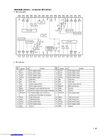
Page 23: ...1 23 BA5936S IC621 6 channel BTL driver 1 Block diagram 2 Pin function ...
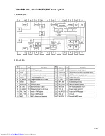
Page 25: ...1 25 LA1823DIP IC1 1chip AM FM MPX tuner system 1 Block diagram 2 Pin function ...
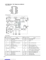
Page 26: ...1 26 LC72136N IC2 PLL Frequency synthesizer 1 Terminal layout 2 Block diagram 3 Pin function ...
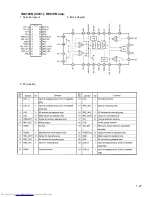
Page 27: ...1 27 TA8189N IC401 REC PB amp 1 Terminal layout 2 Block diagram 3 Pin function ...
Page 28: ...1 28 TC74HC4094AP IC402 8 bit shift and store resister 1 Terminal layout 2 Block diagram ...
Page 29: ...1 29 TDA7440D IC101 Audio processor 1 Terminal layout 2 Block diagram ...


