1-17
Removing the power amp and supply
PCB and the power trans PCB
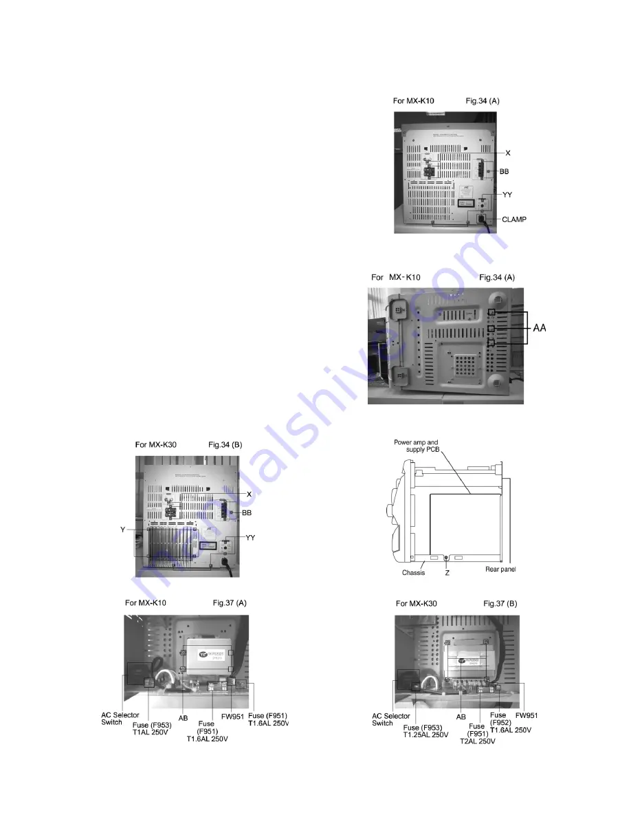
(See Fig. 2, 3, 32, 34 to 37)
Prior to performing the following procedures, remove
the top cover and both sides board.
Also remove heat sink cover.(Fig.4)
1. Remove the two screws "A" connecting the heat sink
cover to the rear panel.(Fig.2, 3)
2. Pull out the heat sink cover toward you.
3. Remove the three (CA-MXK10)/ four(CA-MXK30)screws
"AA" form the (CA-MXK10) chassis /MX-K30 back panel
between the heat sink.
4. Remove the three screws "X" that retain the speaker
terminals and AUX terminal.
5. Remove the screw "YY" and "Y" that retains the rear
panel, and AC switch screw then remove the rear panel.
6. Disconnect the parallel wires from the connectors
FW951 on the power trans PCB.
7. Remove the screw "Z" that retain the power amp and
supply PCB and then remove the assembly.
8. Remove the clamp of AC power cord from the chassis.
9. Remove the four screws "AB" that retain the power
trans PCB and then remove the assembly.
Fig.36
Summary of Contents for MX-K10/30
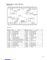
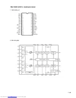
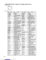
Page 23: ...1 23 BA5936S IC621 6 channel BTL driver 1 Block diagram 2 Pin function ...
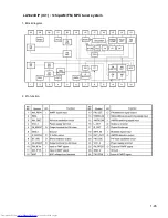
Page 25: ...1 25 LA1823DIP IC1 1chip AM FM MPX tuner system 1 Block diagram 2 Pin function ...
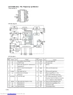
Page 26: ...1 26 LC72136N IC2 PLL Frequency synthesizer 1 Terminal layout 2 Block diagram 3 Pin function ...
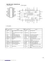
Page 27: ...1 27 TA8189N IC401 REC PB amp 1 Terminal layout 2 Block diagram 3 Pin function ...
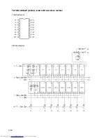
Page 28: ...1 28 TC74HC4094AP IC402 8 bit shift and store resister 1 Terminal layout 2 Block diagram ...
Page 29: ...1 29 TDA7440D IC101 Audio processor 1 Terminal layout 2 Block diagram ...


