background image

2

3

4

5

6

7

9

p

1

8

6

4

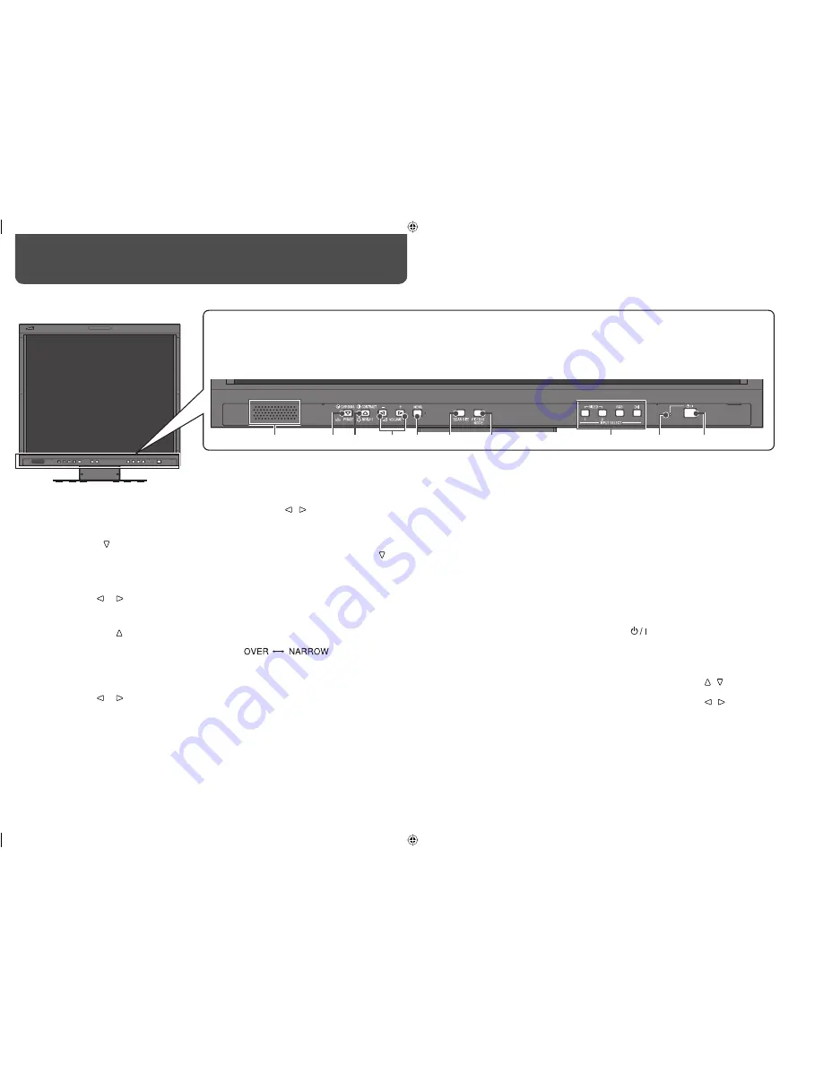
  VOLUME –/+ (  /  ) buttons*

2

Adjusts the volume.

5

  MENU button

Displays the MAIN MENU.
•  To display the SET UP MENU, press   

button while pressing MENU button.

•  For the menu operations, see page 7.

6

  SCAN SIZE button/lamp

Selects the screen size when VIDEO 1 or 
VIDEO 2 is selected for the input.
•  Each time you press the button, the screen 

size changes as follows:

•  When “NARROW” is selected, the lamp 

lights.

•  When “NARROW” is selected, black bars 

appear on the top and the bottom of the 
screen because the aspect ratio of the LCD 
panel is 5:4.

•  This setting is not available for signals from 

a computer is selected for the input.

Daily Operations / Connections 

7

 Front panel

•  “NO EFFECT” is displayed when you press a button which is not available for the current input or signal format (the lamp lights even when the 

function does not actually work).

•  The items controlled by the MAKE system cannot be controlled by the buttons on the front panel (“REMOTE ON” is displayed and the lamps 

do not light).

1

  Speaker (monaural)

The speaker emits the audio signal for the 
selected input.

2

  CHROMA/PHASE ( ) button*

1

Displays the adjustment bar for the picture 
color density or hue.
•  Each time you press the button, the 

adjustment for chroma and phase changes.

•  To adjust, press   or   (

4

) button.

•  The adjustment is memorized for each 

Picture Mode (

7

).

3

  CONTRAST/BRIGHT ( ) button*

1

Displays the adjustment bar for the picture 
contrast or brightness.
•  Each time you press the button, the 

adjustment for contrast and brightness 
changes.

•  To adjust, press   or   (

4

) button.

•  The adjustment is memorized for each 

Picture Mode (

7

).

7

  PICTURE MODE button/lamp

Selects the Picture Mode.*

3

STD.:

 Normal picture

DARK ENHANCED:

 Makes the dark parts of 

the picture clear.

VIVID:

 Makes the picture vivid.

DYNAMIC:

 Makes the picture bright.

•  When “DARK ENHANCED, “VIVID,” or 

“DYNAMIC” is selected, the lamp lights.

•  When RGB or DVI is selected for the input, 

the Picture Mode is fixed to “STD.”

•  When “DYNAMIC” is selected, high 

luminance parts of pictures may not be 
displayed properly. In this case, select 
another Picture Mode.

8

  INPUT SELECT buttons/lamps

Selects an input.

VIDEO 1:

 VIDEO 1 IN or Y/C terminal

VIDEO 2:

 VIDEO 2 IN terminal

RGB:

 RGB terminal*

4

DVI:

 DVI-D terminal

•  The lamp for the selected input lights.

9

  Power lamp

Unlit:

 The monitor is completely off (the AC 

plug is not connected).

Lights in Green:

 The monitor is on or in the 

Gray Back mode (

 “NO SYNC ACTION” in 

“SYNC FUNCTION” on page 12).

Lights in orange:

 The monitor is off (on 

standby).

Flashes in orange:

 The monitor is in the 

Power Save mode (

 “NO SYNC ACTION” in 

“SYNC FUNCTION” on page 12).

p


 button

Turns on and off (on standby) the monitor.

*

1

 When a menu screen or adjustment bar is displayed, 

these buttons work as   /   to select an item.

*

2

 When a menu screen or adjustment bar is displayed, 

these buttons work as   /   to adjust the item or 
select an option.

*

3

 To reset the adjustments for each Picture Mode, see 

“Resetting the Picture Mode” (

 page 7).

*

4

 Before using this input, perform “AUTO ADJUST” (


“AUTO ADJUST” on page 10).

The illustration of the monitor is of LM-H191.

LMH191&171EA_EN.indd   6

LMH191&171EA_EN.indd   6

08.7.8   5:40:19 PM

08.7.8   5:40:19 PM

Summary of Contents for LM-H171

Page 1: ...СПЛУАТАЦИИ 使用说明书 LCD DISPLAY MONITOR LCD DISPLAYMONITOR MONITEUR LCD SCHERMO A CRISTALLI LIQUIDI MONITOR PANTALLA LCD МОНИТОР С ЖК ДИСПЛЕЕМ LCD 显示器 The illustration of the monitor is of LM H191 ESPAÑOL ITALIANO ENGLISH DEUTSCH FRANÇAIS РУССКИЙ 中 文 LMH191 171EA cover1 indd 1 LMH191 171EA cover1 indd 1 08 7 22 5 56 56 PM 08 7 22 5 56 56 PM ...

Page 2: ...gnals 9 Menu Configuration MAIN MENU 10 Menu Configuration SET UP MENU 11 External Control 13 About the external control 13 Using the MAKE TRIGGER system 13 Troubleshooting 14 Specifications 15 General 15 Input output terminals 16 Dimensions 16 ENGLISH The illustration of the monitor is of LM H191 LM H191 LM H171 LMH191 171EA_EN indd 1 LMH191 171EA_EN indd 1 08 7 8 5 40 10 PM 08 7 8 5 40 10 PM ...

Page 3: ... instructions should be followed Fuse For United Kingdom AC 220 240 V For European and Asian countries AC 220 240 V Under the following conditions 1 Turn off the power 2 Unplug this product from the wall outlet 3 Refer service to qualified service personnel a When the product emits smoke or unusual smell b When the product exhibits a distinct change in performance for example no picture or no soun...

Page 4: ...net such as its paint s peeling away be careful about the following Do not wipe the cabinet using solvent such as alcohol thinner or benzine Do not expose the cabinet to any volatile substance such as insecticides Do not allow any rubber or plastic in contact for a long time Do not wipe the cabinet forcefully Wipe stains off the cabinet with a soft cloth If the cabinet gets heavily stained wipe it...

Page 5: ...event the LCD panel from being damaged Be careful not to pinch your fingers in the moving parts When lifting up the stand make sure to align the guidelines for 144 and fasten the screw otherwise the monitor may fall over Place the monitor on a mat to avoid scratching the table surface Do not lift up the stand when the stand plate is attached to the lower position of the stand body To adjust the st...

Page 6: ...nd screws M4 x 10 mm not provided Hook not provided To adjust the stand height To change the stand height change the position of the stand plate as illustrated below after detaching the stand from the monitor For detaching the stand see To detach the stand on page 4 Screw holes for higher position Screw holes for lower position Stand plate Stand plate Higher position Lower position The illustratio...

Page 7: ...justment for contrast and brightness changes To adjust press or 4 button The adjustment is memorized for each Picture Mode 7 7 PICTURE MODE button lamp Selects the Picture Mode 3 STD Normal picture DARK ENHANCED Makes the dark parts of the picture clear VIVID Makes the picture vivid DYNAMIC Makes the picture bright When DARK ENHANCED VIVID or DYNAMIC is selected the lamp lights When RGB or DVI is ...

Page 8: ...ns to make adjustments 4 Press MENU button to return to the previous menu Pressing the button again finishes the menu operation Setup Menu Operations Selected item Operation guide You can reset the following picture adjustments you have made for each Picture Mode Adjustments by the buttons on the front panel SHARPNESS CTI and LTI in the MAIN MENU page 10 1 Press PICTURE MODE button repeatedly to s...

Page 9: ...h the terminals on this monitor and the equipment Plugs should be firmly inserted poor connections could cause noise When unplugging a cord be sure to grasp its plug and pull it out DO NOT connect the power cord until all connections are completed Refer also to the user manual of each piece of equipment 1 AC IN terminal AC power input connector Connect the provided AC power cord to an AC outlet 2 ...

Page 10: ...0x576 50Hz VGA 31 47 59 94 640x480 60Hz VGA_TEXT 31 47 70 08 720x400 70Hz SVGA 35 15 56 25 800x600 56Hz 37 879 60 317 800x600 60Hz XGA 48 363 60 004 1024x768 60Hz 56 476 70 069 1024x768 70Hz WXGA 47 396 59 99 1280x768 60Hz SXGA 63 981 60 02 1280x1024 60Hz Acceptable Not acceptable Some signals may not be displayed normally even if its frequency is within the acceptable range Horizontal vertical fr...

Page 11: ...flickering by adjusting the both settings 000 100 CLOCK PHASE 4 000 063 1Displayed only when VIDEO 1 or VIDEO 2 is selected for the input 2Memorized for each Picture Mode 7 PICTURE MODE button lamp on page 6 3Displayed only when RGB is selected for the input 4Memorized for each signal format For some signals the adjustment may not take effect 5The maximum value is different depending on the incomi...

Page 12: ...ach item of WHITE BALANCE SET Select an item by pressing then adjust the picture while viewing the actual picture reset Restore the default settings for all the items in WHITE BALANCE SET SIZE POSI ADJ 2 Adjusts the size and position of the picture When RGB is selected for the input perform AUTO ADJUST page 10 Item To do Setting value H SIZE 4 Adjust the horizontal picture size 5 10 20 H POSI 4 Ad...

Page 13: ... will not be reset HOUR METER X100h Displays the total hours of use This item is used for maintenance of the monitor The hour is shown in 100 hour unit The hour will not be reset The hour is reset to 000 after the total hours of use have reached to 999 Use time less than 1 minute is not accumulated The menu automatically disappears in about 30 seconds after the previous operation Some items may no...

Page 14: ...g the corresponding pin terminal to the 8th pin terminal GND or opening it When selecting TRIGGER Operate each function by pulse control that is short circuiting the corresponding pin terminal to the 8th pin terminal GND for about 1 second and opening it When changing the input or Picture Mode with the MAKE system only one pin terminal must be short circuited Other pin terminals must be opened Whe...

Page 15: ...e screen after the picture has changed Though the remaining picture will disappear after a while there may be a case that it remains for a long period depending on the length of time the still image was displayed for This is due to the characteristics of the LCD display and is not a malfunction The red spots blue spots and green spots on the panel surface are a normal characteristic of LCD display...

Page 16: ...20 V AC 220 240 V 50 Hz 60 Hz Rated current 0 9 A AC 120 V 0 7 A AC 220 240 V 0 7 A AC 120 V 0 5 A AC 220 240 V External dimensions excluding protruding parts Width 413 mm 16 3 8 413 mm 16 3 8 Height 404 8 mm 16 364 mm 14 3 8 Depth 199 mm 7 7 8 74 mm 3 with the stand without the stand Width 374 mm 14 3 4 374 mm 14 3 4 Height 374 8 mm 14 7 8 334 mm 13 1 4 Depth 199 mm 7 7 8 74 mm 3 with the stand w...

Page 17: ...r PAL DVI D DVI D signal input DVI D connector x 1 compatible with DDC2B RGB Input of analog RGB signal D sub 15 pin x 1 G 1 V p p 75 Ω G on sync 0 3 V p p B R 0 7 V p p 75 Ω H sync TTL V sync TTL C sync TTL TTL LOW 0 V 0 8 V HIGH 2 5 V 5 V Audio AUDIO INPUT VIDEO 1 VIDEO 2 Analog audio signal input 1 line RCA connector 500 mV rms high impedance AUDIO INPUT RGB DVI D Analog audio signal input 1 li...

Page 18: ... 2008 Victor Company of Japan Limited 0708STH MW MT LM H191 LM H171 LCD DISPLAY MONITOR LM H191 171EA_Cover indb 4 LM H191 171EA_Cover indb 4 08 7 10 9 37 51 AM 08 7 10 9 37 51 AM ...

Reviews: