background image

TQB2AA0549

Operating Instructions

Manual de instrucciones

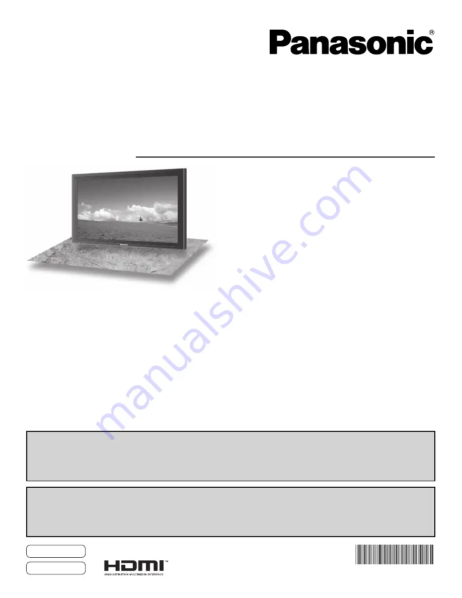
High Definition Plasma Display

Alta definición Pantalla de plasma 

Model No.

No. de Modelo

TH-42PH12U
TH-50PH12U
TH-42PH12L
TH-50PH12L

English

Español

The illustration shown is an image.
Before connecting, operating or adjusting this product, please read these instructions completely.
Please keep this manual for future reference.

La ilustración mostrada es una imagen.
Antes de conectar, utilizar o ajustar este producto, lea completamente este manual de instrucciones;
y guárdelo para consultarlo en el futuro en caso de ser necesario.

For more detailed instructions, refer to the Operating Instructions on the CD-ROM.
To view the Operating Instructions on the CD-ROM, you need a computer equipped with a CD-ROM drive, and 
Adobe

®

 Reader

®

 (Version 7.0 or later is recommended) installed on your computer.

Depending on the operating system or settings on your computer, the Operating Instructions may not start automatically.
In this case, open the PDF file under \MANUAL\PDF manually to view the instructions.

Para obtener instrucciones más detalladas, consulte las instrucciones de manejo contenidas en el CD-ROM.
Para ver las instrucciones de manejo contenidas en el CD-ROM, se necesita un ordenador equipado con una
unidad de CD-ROM, y que tenga instalado Adobe

®

 Reader

®

 (se recomienda la versión 7.0 o posterior).

Dependiendo del sistema operativo o de las configuraciones del ordenador, las instrucciones de manejo pueden no iniciarse automáticamente.
En tal caso, abra manualmente el archivo PDF en \MANUAL\PDF para visualizar las instrucciones.

Contents

Important Safety Instructions  ···········································  3
FCC STATEMENT  ·······························································  4
Safety Precautions  ····························································  5
Maintenance  ·······································································  6
Accessories  ·······································································  7
Connections  ·······································································  8
Power ON / OFF  ·······························································  14

Selecting the input signal  ···············································  16
Basic Controls  ·································································  17
On-Screen Menu Displays  ··············································  19
Specifications  ··································································  20
Panasonic Professional Flat Panel Display Limited Warranty  ··  22
LIMITED WARRANTY STATEMENT  ································  23
Customer Service  ····························································  24

Summary of Contents for TH-42PH12L

Page 1: ...the operating system or settings on your computer the Operating Instructions may not start automatically In this case open the PDF file under MANUAL PDF manually to view the instructions Para obtener...

Page 2: ...O NOT OPEN WARNING To prevent damage which may result in fire or shock hazard do not expose this apparatus to rain or moisture Do not place containers with water flower vase cups cosmetics etc above t...

Page 3: ...nt of the obsolete outlet 10 Protect the power cord from being walked on or pinched particularly at plugs convenience receptacles and the point where they exit from the apparatus 11 Only use attachmen...

Page 4: ...nce that may cause undesired operation FCC CAUTION To assure continued compliance follow the attached installation instructions and use only shielded interface cables when connecting to computer or pe...

Page 5: ...e a permanent image retention to remain on the Plasma Display Examples of still pictures include logos video games computer images teletext and images displayed in 4 3 mode Speakers TY SP42P8W K for T...

Page 6: ...pedestal optional accessory leave a space of 3 15 16 10 cm or more at the top left and right and 2 3 4 7 cm or more at the rear and also keep the space between the bottom of the display and the floor...

Page 7: ...arge short circuit disassemble heat or burn used batteries 5 Battery replacement is necessary when the remote control acts sporadically or stops operating the Plasma Display 6 Do not burn or breakup b...

Page 8: ...e attached cable fixing band through the clip as shown in the figure To secure cables connected to Terminals wrap the cable fixing band around them then pass the pointed end through the locking block...

Page 9: ...accessories Pass the attached cable fixing band through the clip as shown in the figure To secure cables connected to Terminals wrap the cable fixing band around them then pass the pointed end throug...

Page 10: ...dapter for computers with DOS V compatible Mini D sub 15P terminal The computer shown in the illustration is for example purposes only Additional equipment and cables shown are not supplied with this...

Page 11: ...ure to wait for the response for the first command to come from this unit before sending the next command If an incorrect command is sent by mistake this unit will send an ER401 command back to the co...

Page 12: ...ditional equipment and HDMI cables shown are not supplied with this set Pin No Signal Pin No Signal 1 T M D S Data2 11 T M D S Clock Shield 2 T M D S Data2 Shield 12 T M D S Clock 3 T M D S Data2 13 C...

Page 13: ...the COMPONENT RGB IN SELECT setting in the SET UP menu to COMPONENT when COMPONENT signal connection or RGB when RGB signal connection Additional equipment cables and adapter plugs shown are not supp...

Page 14: ...socket outlet first Press the Power switch on the Plasma Display to turn the set on Power On Power Indicator Green Press the button on the remote control to turn the Plasma Display off Power Indicator...

Page 15: ...itching on the unit Following screen will be displayed when the unit is turned on for the first time Select the items with the remote control Unit buttons are invalid OSD LANGUAGE PRESENT TIME SETUP D...

Page 16: ...the component RGB input terminals In 2 screen display the same input mode cannot be selected for the main picture and sub picture Image retention image lag may occur on the plasma display panel when...

Page 17: ...Indicator not illuminated The unit will still consume some power as long as the power cord is still inserted into the wall outlet Standby Red Power ON Green DPMS POWER MANAGEMENT Orange With PC input...

Page 18: ...selected input signal Ex INPUT1A INPUT1B MULTI Window buttons Digital Zoom Remote Control Transmitter AUTO SETUP button Automatically adjusts the position size of the screen SET UP button SOUND butto...

Page 19: ...0 0 2 2 W B LOW B W B HIGH R W B LOW R W B LOW G W B HIGH G W B HIGH B ADVANCED SETTINGS 0 0 2 2 1 2 BLACK EXTENSION AGC GAMMA INPUT LEVEL ADVANCED SETTINGS NORMAL NORMALIZE OFF 2 2 SOUND OUT LEFT CH...

Page 20: ...GA XGA SXGA UXGA compressed Horizontal scanning frequency 15 110 kHz Vertical scanning frequency 48 120 Hz Connection terminals HDMI A B TYPE A Connector 2 COMPONENT RGB IN Y G BNC PB B BNC PR R BNC A...

Page 21: ...SXGA UXGA compressed Horizontal scanning frequency 15 110 kHz Vertical scanning frequency 48 120 Hz Connection terminals AV IN VIDEO IN BNC S VIDEO IN MINI DIN 4PIN AUDIO IN RCA PIN JACK 4 1 0 Vp p 75...

Page 22: ...indicated above Panasonic Professional Display Company referred to as the Warrantor will repair this product and all included accessories with new or refurbished parts free of charge in the USA or Pu...

Page 23: ...age period Proof of product purchase is a condition of warranty service The owner must produce the product purchase receipt or other satisfactory evidence of date of original purchase This warranty do...

Page 24: ...24...

Page 25: ...Note...

Page 26: ...Panasonic Way 1F 10 Secaucus NJ 07094 EASTERN ZONE One Panasonic Way 4E 7 Secaucus NJ 07094 201 348 7621 Mid Atlantic New England One Panasonic Way 4E 7 Secaucus NJ 07094 201 348 7621 Southeast Region...

Reviews: