background image

1-10 (No.MA384<Rev.001>)

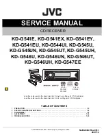
3.1.6 Removing the SWITCH BOARD assembly (See Fig.9, 10 )

(1) Remove the VOLUME KNOB.
(2) Remove the one screw 

L

 and the four screws 

M

 attaching

the REAR COVER. (See Fig.9, 10)

(3) Disengage the nine hooks 

b

 engaged the REAR COVER.

(See Fig.10)

Fig.9

Fig.10

L

hook 

b

hook 

b

M

M

M

Summary of Contents for KD-G541E

Page 1: ...D G546U KD G546UN KD G546UT KD G546UH KD G547EE COPYRIGHT 2007 Victor Company of Japan Limited Lead free solder used in the board material Sn Ag Cu melting point 219 Centigrade Lead free solder used in the board material Sn Cu melting point 230 Centigrade TABLE OF CONTENTS 1 PRECAUTION 1 5 2 SPECIFIC SERVICE INSTRUCTIONS 1 8 3 DISASSEMBLY 1 8 4 ADJUSTMENT 1 24 5 TROUBLESHOOTING 1 25 only for KD G5...

Page 2: ...1 620 kHz LW 144 kHz to 279 kHz FM Tuner Usable Sensitivity 11 3 dBf 1 0 µV 75 Ω 50 dB Quieting Sensitivity 16 3 dBf 1 8 µV 75 Ω Alternate Channel Selectivity 400 kHz 65 dB Frequency Response 40 Hz to 15 000 Hz Stereo Separation 30 dB MW Tuner Sensitivity Selectivity 20 µV 35 dB LW Tuner Sensitivity 50 µV CD PLAYER SECTION Type Compact disc player Signal Detection System Non contact optical pickup...

Page 3: ...531 kHz to 1 602 kHz FM Tuner Usable Sensitivity 11 3 dBf 1 0 µV 75 Ω 50 dB Quieting Sensitivity 16 3 dBf 1 8 µV 75 Ω Alternate Channel Selectivity 400 kHz 65 dB Frequency Response 40 Hz to 15 000 Hz Stereo Separation 30 dB AM Tuner Sensitivity 20 µV Selectivity 35 dB CD PLAYER SECTION Type Compact disc player Signal Detection System Non contact optical pickup semiconductor laser Number of Channel...

Page 4: ...144 kHz to 279 kHz FM Tuner Usable Sensitivity 11 3 dBf 1 0 µV 75 Ω 50 dB Quieting Sensitivity 16 3 dBf 1 8 µV 75 Ω Alternate Channel Selectivity 400 kHz 65 dB Frequency Response 40 Hz to 15 000 Hz Stereo Separation 30 dB MW Tuner Sensitivity Selectivity 20 µV 35 dB LW Tuner Sensitivity 50 µV CD PLAYER SECTION Type Compact disc player Signal Detection System Non contact optical pickup semiconducto...

Page 5: ...urrs formed during molding may be left over on some parts of the chassis Therefore pay attention to such burrs in the case of preforming repair of this system Please use enough caution not to see the beam directly or touch it in case of an adjustment or operation check ...

Page 6: ...r diode in the optical pickup The tester s internal power source can easily destroy the laser diode 1 3 Handling the traverse unit optical pickup 1 Do not subject the traverse unit optical pickup to strong shocks as it is a sensitive complex unit 2 Cut off the shorted part of the flexible cable using nippers etc after replacing the optical pickup For specific details refer to the replacement proce...

Page 7: ...oduct uses visible and or invisible laser radiation and is equipped with safety switches which prevent emission of radiation when the drawer is open and the safety interlocks have failed or are defeated It is dangerous to defeat the safety switches 5 CAUTION If safety switches malfunction the laser is able to function 6 CAUTION Use of controls adjustments or performance of procedures other than th...

Page 8: ...taching the FRONT CHASSIS assembly See Fig 1 2 Remove the two screws B attaching the both side of the FRONT CHASSIS assembly See Fig 2 3 Disengage the four hooks a engaged the both side of the FRONT CHASSIS assembly See Fig 2 Fig 1 Fig 2 3 1 2 Removing the HEAT SINK See Fig 3 4 1 Remove the four screws C and the two screws D attaching the HEAT SINK See Fig 3 2 Remove the two screws E and the one s...

Page 9: ...e MAIN BOARD assembly See Fig 6 7 1 Remove the two screws H and the two screws J attaching the MAIN BOARD assembly See Fig 6 7 2 Disconnect the connector CN501 connected to MAIN BOARD assembly and CD MECHANISM assembly See Fig 7 Fig 6 Fig 7 3 1 5 Removing the CD MECHANISM assembly See Fig 8 1 Remove the three screws K attaching the CD MECHANISM assembly Fig 8 G H J CN501 K K ...

Page 10: ...SWITCH BOARD assembly See Fig 9 10 1 Remove the VOLUME KNOB 2 Remove the one screw L and the four screws M attaching the REAR COVER See Fig 9 10 3 Disengage the nine hooks b engaged the REAR COVER See Fig 10 Fig 9 Fig 10 L hook b hook b M M M ...

Page 11: ... Figs 1 and 2 1 From the both side of the CD mechanism assembly remove the four screws A attaching the top cover See Fig 1 2 Lift the front side of the top cover and move the top cover backward to release the two joints a See Figs 1 and 2 Fig 1 Fig 2 A A A a Top cover A a Top cover ...

Page 12: ...static electricity See Fig 3 1 From the bottom side of the CD mechanism assembly remove the screw C attaching the base board See Figs 3 and 4 2 Solder the short land c on the pickup See Fig 3 3 Disconnect the flexible wire from the connector on the pickup See Fig 3 4 Remove the base board from the joints d of the frame in the direction of the arrow See Figs 3 and 4 Reference Remove the wires from ...

Page 13: ... Remove the chassis unit from the dampers on the frame in an upward direction See Fig 6 Note Pay attention to misuse and loss of each spring See Fig 5 When reassembling make sure that the three shafts on the underside of the chassis unit are inserted to the dampers certainly See Fig 6 Fig 5 Fig 6 Front suspension spring Rear suspension spring Rear suspension spring Front suspension spring Chassis ...

Page 14: ...he clamper assembly See Figs 7 and 8 Remove the top cover Move the clamper assembly in the direction of the arrow to release the joints f from the chassis unit Fig 7 Fig 8 f f Clamper assembly Chassis unit f f Clamper assembly Chassis unit ...

Page 15: ...s unit From the bottom side of the chassis unit remove the screw D and take out the loading feed motor assembly in the direction of the arrow Reference Remove the wires from the soldered sections g of the loading feed motor assembly as required Fig 9 D Loading feed motor assembly g Loading feed motor assembly Chassis unit ...

Page 16: ... screw holder as required See Fig 12 7 Release the claw k in the direction of the arrow to remove the feed sub holder See Fig 12 3 2 8 Reattaching the pickup See Figs 10 to 13 1 Reattach the feed sub holder to the pickup See Fig 12 2 Reattach the feed screw holder to the pickup using the screw G See Fig 12 3 Reattach the feed screw assembly and pu shaft holder A to the pickup as before See Fig 11 ...

Page 17: ...m in the direction of the arrow to remove the trigger arm base from the section s in the direction of the arrow 4 Remove the trigger arm from the section t Fig 14 3 2 10 Removing the top plate assembly See Fig 15 Remove the top cover base board chassis unit clamper assembly and trigger arm 1 Remove the screw H attaching the top plate assembly 2 Move the top plate assembly in the direction of the a...

Page 18: ... link gear L in the direction of the arrow 3 Move the mode switch in the direction of the arrow 1 to remove the sections z of the top plate assembly 4 Move the mode switch in the direction of the arrow 2 and remove the mode switch from the sections aa ab Note When reattaching the link gear L attach it after aligning the hole ac of the link gear L to the hole ac of the link gear R Reference When re...

Page 19: ...lect arm R from the sections ag See Fig 17 5 From the bottom side of the top plate assembly remove the select lock arm spring from the section ah See Fig 18 6 From the top side of the top plate assembly remove the section aj of the select lock arm from the top plate assembly at first and remove the sections ak am of the select lock arm from the top plate assembly See Fig 18 Note When removing the ...

Page 20: ... the lock arm assembly from the joint at of the cam plate L assembly See Fig 19 5 From the right side of the lock arm assembly remove the loading roller spring L from the section au See Fig 20 6 From the top side of the lock arm assembly remove the loading roller spring R in the direction of the arrow and remove the loading roller assembly See Fig 20 7 Remove the roller guide R HL washer and rolle...

Page 21: ...ar 2 See Fig 22 3 Pull out the change arm See Fig 22 4 Move the change gear plate rivet assembly in the direction of the arrow 2 to remove the section av of the change gear plate rivet assembly from the chassis unit while moving the change lock lever in the direction of the arrow 1 See Fig 23 5 Pull out the change gear 3A and change gear 3B from the change gear plate rivet assembly See Fig 23 Fig ...

Page 22: ...mbly top plate assembly loading roller assembly and cam plate R 1 Remove the slide hook rivet assembly and trigger rack spring from the chassis unit See Fig 25 2 From the bottom side of the chassis unit pull out the loading gear 1 See Fig 26 3 Remove the trigger control spring from the sections ay az See Fig 26 4 Take out the trigger rack plate from the chassis unit See Fig 26 Reference When attac...

Page 23: ...gear 2 in the direction of the arrow 2 while pulling the trigger arm in the direction of the arrow 1 and let the pickup move in the direction of the arrow 3 See Fig 28 3 Slide the spindle motor assembly in the direction of the arrow and take out it in an upward direction from the chassis unit See Fig 28 Reference Remove the wires from the soldered sections c on the base board and remove them from ...

Page 24: ... and Bass Treble volume lndication 0 Loudness OFF 4 4 Dummy load Exclusive dummy load should be used for AM and FM For FM dummy load there is a loss of 6dB between SSG output and antenna input The loss of 6dB need not be considered sincedirect reading of figures are applied in this working standard 4 5 How to connect the extension cable for adjusting Caution Be sure to attach the heat sink and rea...

Page 25: ... 1 3 5 7 2 4 6 8 VI GY WH GN VI BK GY BK WH BK GN BK 7 RD 16 YL 8 BK 5 BL WH 13 BR 3 GN 11 GN BK 2 VI 10 VI BK 4 WH 12 WH BK 1 GY 9 GY BK RD RD 7 YL 4 8 5 2 8 5 2 7 1 6 3 4 BK RD BL WH BR Black Red Blue White Brown GN Green VI Violet GY Gray YL Yellow RR Rear Right FR Front Right FL Front Left RL Rear Left REMOTE Remote ACC TEL ACC Line Telephone Muting GND Ground MEMORY Memory Backup Battery ILL ...

Page 26: ...5 KD G546 BK YL RD BL WH GN BK VI VI BK WH BK GN GY BK WH 2 16 1 8 5 7 12 10 3 9 11 GY BK RD BL WH Black Red Blue White GN VI Violet GY Gray YL Yellow Green 4 7 6 5 4 3 2 1 16 15 14 13 12 11 10 9 BK RD BL BL WH WH GN VI GY YL NC NC WH BK GN BK VI BK GY BK 8 NC 6 BL ...

Page 27: ... No MA384 Rev 001 1 27 ...

Page 28: ... No MA384 Rev 001 VPT Printed in Japan Victor Company of Japan Limited Mobile Entertainment Business Group Mobile Entertainment Category 10 1 1chome Ohwatari machi Maebashi city 371 8543 Japan ...

Page 29: ... G541EX KD G541EY KD G541EU KD G544UI KD G545U KD G545UN KD G545UT KD G545UH KD G546U KD G546UN KD G546UT KD G546UH KD G547EE COPYRIGHT 2007 Victor Company of Japan Limited Lead free solder used in the board material Sn Ag Cu melting point 219 Centigrade Lead free solder used in the board material Sn Cu melting point 230 Centigrade only for KD G547 only for KD G541 KD G547 ...

Page 30: ...r on some parts of the chassis Therefore pay attention to such burrs in the case of preforming repair of this system Safety precaution Please use enough caution not to see the beam directly or touch it in case of an adjustment or operation check ...

Page 31: ... CD servo control section LCD AUX Jack Key control section Function section S702 DETACH SW DETACH ANT ANT STEERING Q976 Q977 PS2 PS2 POWER E2PROM_DI E2PROM_DO E2PROM_CLK X702 32 768kHz D601 D602 D604 to D622 LIGHTING DISPLAY Q6001 to Q6003 SWITCHING DIMOUT VDD5V D645 D646 DIMMER Q640 Q641 DIMMER CTRL ILM 10V EJECT S2441 EJECT SW D2441 to D2443 LED SW1 SW2 CN501 CN001 CD MECHA CD PICK UP MUTE SUB M...

Page 32: ... 1 390p 10 25 CRS03 W 330p 0 01 QQR1809 001 UDZW5 6B X 560p 33p 33p 2 2k QSW0648 001Z MA22D39 X 10 16 0 01 390p 1SS355W X 100 47 6 3 4 7K 1SS355W X RT6N430C X MC2836 X 0 01 2 2 50 1 1 10 16 6 8K 0 22 6 8K 330 6 3 100K 56p 56p CRS03 W QTE1C57 106Z 8 2K 8 2K MC2836 X 4 7K 10 25 47 16 0 1 UDZW6 2B X 100 MC2836 X RT1N141C X 5 6P 0 47U 3 3K 4 7K 4 7K 10k 10k 4 7K 4 7 47 6 3 MA22D39 X 220 10 2 2k 27K 47...

Page 33: ... 1 NJM4565E X 820 22k 22k 10k 820p 820p 3300p 39K 4 7k 0 1 47 6 3 QTE0J57 476Z QTE1A57 107Z 0 1 0 33 47 6 3 47 6 3 4 7 ISA1530AC1 R X NI 2200p 220 6 3 NI NI 11k NI 20k 10k NI 8 2k 8 2k 5 1k 3 3K 5 6K 5 6k 0 0012 1K 0 0018 5 6K 220 10 0 1 47 6 3 0 1 47K 100 6 3 0 1 0 1 GND GND GND VR VF2 VT2 VT2 VT1 VT1 VF1 VF1 VF2 MD MD TRK TRK LD LD SP SP FEED VF2 FEED RFVDD GND VT2 SW1 VT1 SW2 VF1 PSW VR SPINDLE...

Page 34: ...1M1 17W QLD0519 001 QNS0215 001 QNS0245 001 FOR U UI VERSION FOR E EE VERSION AUX 2SA1365 F X 2SA1365 F X 4 7K 1k 1 330 470 1 2k NI 0 1 220k 1k CL 197HG5 CD X 820 560 1 2k UDZW5 1B X 1 2k MA8062 M X 1 2k 560 1 2k 560 1 2k 560 MA8062 M X 680 4 7K 0 022 150p 330 1 2k 680 MA8062 M X TO CN742 NBE20JM 475X 560 10K 560 1 2k NCB20JM 475X 1 2k 1 2k 820 220 1 2k 1 2k 1 2k 1 2k 560 1 2k 1 2k 1SS355W X 1 2k ...

Page 35: ...21 L122 L701 L702 L901 Q321 Q331 Q341 Q351 Q501 Q521 Q782 Q784 Q785 Q891 Q892 Q976 Q977 R1 R2 R3 R4 R5 R6 R7 R11 R71 R72 R73 R74 R76 R81 R82 R91 R92 R120 R121 R161 R162 R163 R164 R165 R166 R167 R168 R169 R170 R171 R172 R173 R174 R305 R322 R323 R332 R333 R342 R343 R352 R353 R363 R367 R383 R387 R500 R501 R502 R503 R505 R506 R507 R508 R509 R510 R511 R512 R513 R514 R515 R516 R517 R518 R519 R520 R521 R...

Page 36: ...15 S601 S602 S603 S604 S605 S606 S607 S608 S609 S610 S611 S612 S613 S614 S616 S617 LCD1 C601 C602 C603 C611 C621 C622 C681 C682 C691 C692 R669 C6001 J602 R683 D641 D642 D643 D645 D646 R684 R685 D691 D692 D6001 D6002 EN601 IC601 IC602 J601 K691 R686 L691 Q6001 Q6002 Q6003 R607 R687 R688 R672 R671 R623 R628 R629 R630 R631 R632 R633 R634 R635 R636 R637 R638 R639 R640 R641 R642 R643 R644 R645 R646 R64...

Page 37: ... M E M O ...

Page 38: ... No MA384SCH Printed in Japan VPT Mobile Entertainment Business Group Mobile Entertainment Category 10 1 1chome Ohwatari machi Maebashi city Gumma ken 371 8543 Japan Victor Company of Japan Limited ...

Page 39: ...mbly and parts list Block No M1 CD mechanism assembly and parts list Block No MB Electrical parts list Block No 01 03 Packing materials and accessories parts list Block No M3 3 2 3 6 3 11 3 18 KD G541E KD G541EX KD G541EY KD G541EU KD G544UI KD G545U KD G545UN KD G545UT KD G545UH KD G546U KD G546UN KD G546UT KD G546UH KD G547EE MA384 ...

Page 40: ...list Switch board B Model TN2007 1026 S M MY008 Block No M M M 1 Function board 13 15 52 37 38 51 54 35 6 6 17 20 48 60 36 6 49 44 50 47 19 16 70 5 12 39 54 55 53 54 58 62 5 13 1 14 41 46 45 40 42 43 30 34 25 18 32 23 28 69 Except EE ver Only UT ver ...

Page 41: ...3 3 Main board B C C Only E series Function board 31 27 29 3 4 26 61 24 10 18 68 63 54 55 8 9 8 8 65 64 58 62 59 56 57 7 7 66 33 11 2 19 34 32 22 28 21 67 The parts without symbol number are not service ...

Page 42: ... ASSY 541E 541EX 541EY 541EU 35 GE33101 004A FRONT PANEL ASSY 544UI 35 GE33101 001A FRONT PANEL ASSY 545U 545UN 545UT 545UH 35 GE33101 005A FRONT PANEL ASSY 546U 546UN 546UT 546UH 35 GE33101 006A FRONT PANEL ASSY 547EE 36 GE33088 004A FINDER ASSY 541E 541EX 541EY 541EU 547EE 36 GE33088 001A FINDER ASSY 544UI 545U 545UN 545UT 545UH 546U 546UN 5 46UT 546UH 37 GE40407 001A SEARCH BTN LENS 38 GE33079 ...

Page 43: ...9 001A LIGHTING SHEET 60 GE40431 001A REMOTE SHEET 61 GE32954 001A NAME PLATE 541E 541EX 541EY 541EU 61 GE32960 001A NAME PLATE 544UI 61 GE32957 001A NAME PLATE 545U 545UN 545UT 545UH 61 GE32963 001A NAME PLATE 546U 546UN 546UT 546UH 61 GE32966 001A NAME PLATE 547EE 62 QLD0519 001 LCD MODULE 63 QNZ0964 001 RUBBER CONNECTO 64 QMFZ063 150 J1 FUSE 15A 65 GE40396 002A REG BRACKET 66 GE40354 001A IC BR...

Page 44: ... 51 105 43 42 61 46 111 121 12 120 4 45 120 48 47 49 59 122 12 20 16 27 32 80 93 87 86 81 112 79 11 123 15 102 14 13 124 33 36 24 25 26 126 35 63 104 125 64 99 11 28 106 21 23 22 92 124 120 91 90 88 89 1 78 130 71 76 74 75 72 64 62 63 120 108 58 110 2 120 3 100 77 Block No M M M B a a ...

Page 45: ...PR 50 30350811T LINK GEAR L 51 30350812T LINK GEAR R 52 30350813T LINK GEAR SPR 58 19501403T WIRE CLUMPER 59 30321013T WIRE CLAMPER 61 30351001T WIRE CLAMPER 62 30351008T MODE SW WIRE 63 30351003T REST SW WIRE 64 30351004T LD WIRE 71 30321137T LDG ROLLER x2 72 30321143T COLLAR SCREW 74 30351101T LOCK ARM 75 30351102T LD ROLLER SPR R 76 30351103T LD ROLLER SPR L 77 30351105T ROLLER GUIDE R 78 30351...

Page 46: ...3 8 124 9P0420047T SCREW x2 125 9P0420067T SCREW 126 9P0420087T SCREW 127 9C0420257T SCREW 130 9W0513060T HL WASHER Symbol No Part No Part Name Description Local ...

Page 47: ...3 9 Grease point 1 2 TNG 87 TN 4456 TNS 925R GP 501MK 104 4 101 44 43 74 grease 1 two sides back side back side back side ...

Page 48: ...3 10 Grease point 2 2 102 106 grease TNG 87 TN 4456 TNS 925R G 322 25 out side 26 33 27 16 111 79 90 92 99 93 back side TR CONTROL SPR side CHF LOCK PLT 50 51 105 ...

Page 49: ...ISTOR 547EE Q976 RT1N141C X TRANSISTOR Q976 or UN2211 X TRANSISTOR Q976 or DTC114EKA X TRANSISTOR 547EE Q977 ISA1530AC1 R X TRANSISTOR Q977 or 2SB709A QR X TRANSISTOR 541E 541EX 541EY 541EU 544UI 545U 545UN 545UT 545U H 546U 546UN 546 UT 546UH Q977 or 2SB709A R X TRANSISTOR 547EE D1 MA111 X SI DIODE D1 or 1SS355W X SI DIODE D2 MA111 X SI DIODE D2 or 1SS355W X SI DIODE D251 MA111 X SI DIODE D251 or...

Page 50: ...NCB31EK 223X C CAPACITOR 0 022uF 25V K C326 QFV91HJ 474Z MF CAPACITOR 0 47uF 50V J C365 QEKJ1HM 475Z E CAPACITOR 4 7uF 50V M C366 QEKJ1HM 475Z E CAPACITOR 4 7uF 50V M C385 QEKJ1HM 475Z E CAPACITOR 4 7uF 50V M C386 QEKJ1HM 475Z E CAPACITOR 4 7uF 50V M C501 QEKJ0JM 227Z E CAPACITOR 220uF 6 3V M C503 QEKJ1AM 227Z E CAPACITOR 220uF 10V M C504 NCB31EK 104X C CAPACITOR 0 1uF 25V K C511 NCB31HK 222X C CA...

Page 51: ... R173 NRSA63J 472X MG RESISTOR 4 7kΩ 1 16W J R174 NRSA63J 222X MG RESISTOR 2 2kΩ 1 16W J R251 NRSA63J 101X MG RESISTOR 100Ω 1 16W J R252 NRSA63J 821X MG RESISTOR 820Ω 1 16W J R253 NRSA63J 333X MG RESISTOR 33kΩ 1 16W J R305 NRSA63J 102X MG RESISTOR 1kΩ 1 16W J R322 NRSA63J 821X MG RESISTOR 820Ω 1 16W J R323 NRSA63J 101X MG RESISTOR 100Ω 1 16W J R332 NRSA63J 821X MG RESISTOR 820Ω 1 16W J R333 NRSA63...

Page 52: ...8W J 547EE R804 NRSA63J 392X MG RESISTOR 3 9kΩ 1 16W J 541E 541EX 541EY 541EU 544UI 545U 545UN 545UT 545U H 546U 546UN 546 UT 546UH R805 NRSA63J 0R0X MG RESISTOR 0Ω 1 16W J R806 NRSA63J 102X MG RESISTOR 1kΩ 1 16W J 541E 541EX 541EY 541EU 544UI 545U 545UN 545UT 545U H 546U 546UN 546 UT 546UH R806 NRSA63J 0R0X MG RESISTOR 0Ω 1 16W J 547EE Symbol No Part No Part Name Description Local R807 NRSA63J 10...

Page 53: ...1 16W J R608 NRSA63J 821X MG RESISTOR 820Ω 1 16W J R609 NRSA63J 122X MG RESISTOR 1 2kΩ 1 16W J R610 NRSA63J 182X MG RESISTOR 1 8kΩ 1 16W J R611 NRSA63J 272X MG RESISTOR 2 7kΩ 1 16W J R612 NRSA63J 392X MG RESISTOR 3 9kΩ 1 16W J R613 NRSA63J 821X MG RESISTOR 820Ω 1 16W J R614 NRSA63J 821X MG RESISTOR 820Ω 1 16W J R615 NRSA63J 103X MG RESISTOR 10kΩ 1 16W J R628 NRSA63J 122X MG RESISTOR 1 2kΩ 1 16W J ...

Page 54: ... S605 NSW0206 001X TACT SWITCH S606 NSW0206 001X TACT SWITCH S607 NSW0206 001X TACT SWITCH S608 NSW0206 001X TACT SWITCH S609 NSW0206 001X TACT SWITCH S610 NSW0206 001X TACT SWITCH S611 NSW0206 001X TACT SWITCH S612 NSW0206 001X TACT SWITCH S613 NSW0206 001X TACT SWITCH S614 NSW0206 001X TACT SWITCH S615 NSW0308 001X TACT SWITCH S616 NSW0206 001X TACT SWITCH S617 NSW0206 001X TACT SWITCH Symbol No...

Page 55: ...3 17 MEMO ...

Page 56: ...s without symbol number are not service KIT A10 A11 A12 A13 A14 A16 A17 P7 P6 P2 P2 P3 P1 P5 A18 A15 A1 A2 A3 A4 A5 A6 A7 P4 Only U A1 A4 A7 A20 P4 Only EE A1 A4 A7 P4 UH UN UT UI A1 A2 A4 A5 A7 A19 A20 P4 E EU EX EY A1 A2 A4 A5 A7 P4 Only EU A8 A9 Only U series ...

Page 57: ...007A INST MANUAL KOR CHI TAIWAN ARA PER 545U 546U A 6 GET0496 008A INST MANUAL RUS 545U 546U A 7 LVT1672 002A INST SHEET 541E 541EX 541EY 541EU 544UI 545U 54 5UN 545UT 545UH 546U 546UN 546UT 54 6UH A 8 GE20137 003A MOUNTING SLEEVE A 9 GE20218 003A TRIM PLATE 541E 541EX 541EY 541EU A 9 GE20235 005A TRIM PLATE 544UI 545U 545UN 545UT 545UH A 9 GE20235 008A TRIM PLATE 546U 546UN 546UT 546UH A 9 GE2021...

Reviews: