


(No.MA425<Rev.001>)1-9
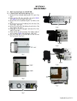
3.1.5 Removing the Key board (See Fig.14)
(1) Remove the Volume knob.
(2) Remove the six screws
L
attaching the Rear cover.
Fig.14
3.1.6 Removing the LCD monitor (See Fig.15 to 18)
There are two ways of methods to exclude monitor block.
Method 1: Press [OPEN] button.
Method 2: After remove the Top chassis, supply voltage approx
3.0V to Motor (See Fig.15)
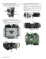
(1) Remove the two screws
M
attaching the FPC cover. (See
Fig.16)
(2) Remove the two screws
N
and two screws
P
attaching the
L panel cover. (See Fig.16)
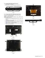
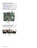
(3) Disconnect the FPC from drive unit connected to connector
CON1
of the TFT board. (See Fig.17)
(4) Remove the six screws
Q
attaching the both side of the
Screen panel. (See Fig.18)
Fig.15
Fig.16
Fig.17
Fig.18
L
L
Motor
approx 3.0V
M
M
N
P
P
N
L panel cover
FPC cover
CON1
FPC
Q


