


1-8 (No.MA425<Rev.001>)
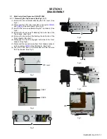
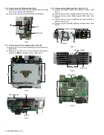
3.1.2 Removing the USB board (See Fig.8)
(1) Disconnect the connector wire from Main board connected
to connector
CON1
of the USB board.
(2) Remove the two screws
E
attaching the USB board.
Fig.8
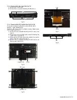
3.1.3 Removing the CD mechanism (See Fig.9, 10)
(1) Remove the four screws
F
attaching the CD mechanism.
(See Fig.9)
(2) Disconnect the FPC from CD mechanism connected to
connector
CON16
of the Main board. (See Fig.10)
Fig.9
Fig.10
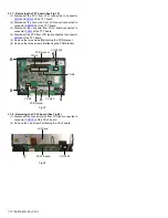
3.1.4 Removing the Main board (See Fig.11 to 13)
(1) Remove the Signal cables from Bottom chassis. (See
Fig.11)
(2) Remove the two screws
G
attaching the FAN. (See Fig.11)
(3) Remove the two screws
H
attaching the FAN cover. (See
Fig.11)
(4) Remove the two screws
J
attaching the Heat sink with IC
bracket. (See Fig.12)
(5) Remove the two screws
K
attaching the Main board. (See
Fig.13)
Fig.11
Fig.12
Fig.13
CON1
USB board
E
F
F
CON16
CD mechanism
FPC
Signal cables
FAN cover
G
H
H
J
Heat sink
IC bracket inside
Main board
K


