background image

E-84

12. FEATURES OF THE CAMERA SECTION

12-3 Adjusting the Shutter Speed

MONITOR

EDITSEARCH

FILTER

STATUS

SHUTTER

MENU

AUTO IRIS

BACK L
NORMAL
SPOT L

STRETCH
NORMAL
COMPRESS

FULL AUTO

BLACK

LOLUX

MODE

POWER

ON

OFF

VTR

OPEN

VTR

CAM

1

3200K
5600K
5600K
5600K

ND

/

/ ND

2
.3
.4

1 8

1 64

CH-1

AUDIO INPUT

AUDIO SELECT

CH-2

CH-1

CH-2

FRONT

REAR

AUTO

MANUAL

AUDIO
LEVEL

CH-1

CH-2

PULL

OPEN

LCD BRIGHT

DISPLAY

STA

SHUTTER

MENU

 ––– CAMERA OPERATION –––
 SHUTTER           STEP
 FAW               NONE 
 GAIN L            0dB
 GAIN M            6dB
 GAIN H            9dB

 SMOOTH TRANS      OFF
 SPOT L/BACK L     MIDDLE
 ASPECT RATIO      4:3
 PAGE BACK

 LOLUX GAIN        30dB

      SHUTTER 1/1000

      SHUTTER OFF

Indication of initial shutter
speed value

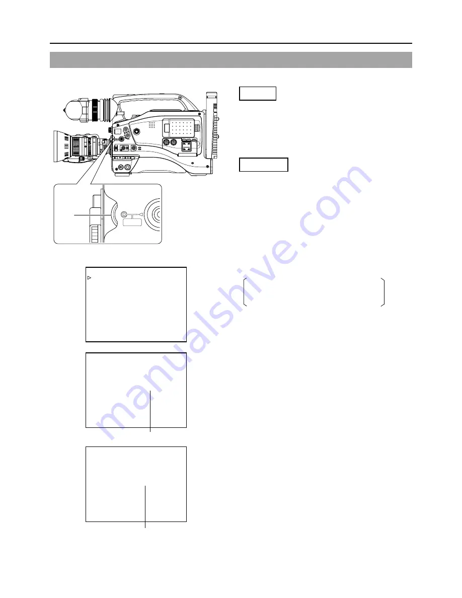
Adjust the shutter speed to obtain special effects or when shooting scenes with slow-moving subjects.

Setting

Set the SHUTTER item on the CAMERA OPERATION
menu screen.

STEP

: The shutter speed is changed in fixed steps.

VARIABLE : The shutter speed is changed with variable scan.

This setting is used for shooting the screen
image on a computer monitor, etc.

Operation

1.

Rotate the SHUTTER dial while the normal screen is shown.
(when menu screens are not displayed).
(If “SHUTTER OFF” is displayed, press the SHUTTER dial.)

The current shutter speed is shown on the LCD monitor
or in the viewfinder for approximately 3 seconds.

2.

Rotate the SHUTTER dial while the shutter speed is shown.
Rotating the dial downward makes the shutter slower, and
rotating it upward makes it faster.

3.

Stop rotating the SHUTTER dial when the desired shutter
speed is indicated. The set shutter speed value is displayed
for about 3 seconds on the LCD monitor or in the viewfinder.
Setting range
STEP: 1/6.25, 1/12.5, 1/25, 1/50, 1/120, 1/250,

1/500, 1/1000, 1/2000, 1/4000, 1/10000

VARIABLE: 1/50.1 Hz to 1/2067.8 Hz

To return the shutter speed to the initial setting, press
the SHUTTER dial.

Initial setting: OFF (“SHUTTER OFF” is indicated on the
screen.)

SHUT-
TER
dial

CAMERA OPERATION menu screen

Shutter speed indication

Summary of Contents for GY-DV5000

Page 1: ...N GY DV5000 GY DV5001 DV CAMCORDER DV CAMKORDER CAMESCOPE DV CÁMARA DE VÍDEO DIGITAL VIDEOCAMERA DIGITALE INSTRUCTIONS BEDIENUNGSANLEITUNG MANUEL D INSTRUCTIONS INSTRUCCIONES ISTRUZIONI The illustration shows the GY DV5000 GY DV5001 DV Camcorder with the optional lens and viewfinder Microphone holder Microphone attached Thank you for purchasing this JVC product Before operating this unit please re...

Page 2: ... can be used in the following environments residential area in houses or rural area commercial and light industry e g offices or theatres urban outdoors In order to keep the best performance and furthermore for electromagnetic compatibility we recommend to use cables not exceeding the following length Caution Where there are strong electromagnetic waves or magnetism for example near a radio or TV ...

Page 3: ...CTRIC SHOCK DO NOT EXPOSE THIS APPLIANCE TO RAIN OR MOISTURE This unit should be used with 12V DC only CAUTION To prevent electric shocks and fire hazards do NOT use any other power source CAUTION To prevent electric shock do not open the cabinet No user serv iceable parts inside Refer servicing to qualified service personnel ...

Page 4: ...igh S N is retained Enables shooting at normal indoor illumination eliminating the need for extra illumination LOLUX for 0 2 lux F1 4 illumination Employment of LOLUX mode ensures 36 dB gain This is ideal for difficult shooting conditions with almost no illumination The gain up value can be selected in the menu Multi Zone Auto Iris Detection Circuit Multi zone auto iris detection circuit ensures o...

Page 5: ...ing Recording 51 7 SHOOTING OPERATION 7 1 Basic Recording Operation 52 7 2 Searching for Recorded Scenes Edit Search 54 7 3 If the Record Standby Mode Continues 55 7 4 Checking Recorded Contents in Record Standby Mode Recording Check Function 55 7 5 HEADER REC Function 56 7 6 Recording the Colour Bars 58 8 PLAYBACK MODE 8 1 Playback Procedure 59 8 2 Fast Forward Rewind 60 8 3 Search 60 8 4 Blank S...

Page 6: ...Do not exceed 15 V DC in any case or the unit could be damaged Allowable ambient temperature and humidity Be sure to use the unit within the allowable temperature range of 0 C to 40 C and a relative humidity of 30 to 80 Using the unit at a temperature or humidity outside the allowable ranges could result not only in malfunction but the impact on the CCD elements could be serious as small white spo...

Page 7: ...e data should be considered as a reference Time management The accumulated running time of the unit can be confirmed with the hour meter display which shows the accumulated drum running time For details see HOUR METER DISPLAY on page 94 For consultations related to the maintenance planning or cost please contact the person in charge of professional video equipment at your nearest JVC authorized se...

Page 8: ...s etc Do not continue to use a dirty or damaged tape as this will reduce the rotary head life Videocassette tapes with the or symbol are provided with a switch on the back to prevent accidental erasure Slide the switch to SAVE to protect the required recording in the tape from being overwritten To record on the tape slide the switch to REC REC SAVE Switch For recording and storing videotapes in th...

Page 9: ...ding in fine mesh patterns White dots High temperatures can cause CCD sensor pixels to produce the effect of white dots in the image This condition is conspicuous especially when gain is applied This is a characteristic of the charged coupled device CCD As far as possible use the unit under conditions where the temperature of the unit does not increase 1 7 Characteristic CCD Phenomena Do not leave...

Page 10: ...ference for manual adjustment of the lens iris Zebra patterns are also displayed during colour bar display when this switch is set to ON See Zebra Pattern Display during Manual Adjustment on page 83 The default value is 70 80 The luminance level can be changed with the ZEBRA setting in the LCD VF menu screen See ZEBRA item on page 75 While this switch is pressed to the SKIN AREA side the colour to...

Page 11: ...roximately ten seconds The depth of field can be reduced and the lens focusing can be adjusted more accurately 9 Lens mounting ring Lens lock lever Hold the lens and use the lever to turn the ring anticlockwise to release lens To mount lens make sure the lens guide pin fits well and then turn the ring clockwise until firm See Attaching the Zoom Lens on page 30 0 FILTER Colour temperature conversio...

Page 12: ...hutter speed indicator is shown See Adjusting the Shutter Speed on page 84 Camera Setting Section GAIN GAIN OUTPUT OUTPUT CAM BARS ON OFF PRST B A AUT UTOKNEE OKNEE WHT BAL MODE M L H MONITOR EDITSEARCH FILTER STATUS SHUTTER MENU AUTOIRIS BACK L NORMAL SPOT L STRETCH NORMAL COMPRESS FULLAUTO BLACK LOLUX MODE POWER ON OFF VTR VTR CAM 1 3200K 5600K 5600K 5600K ND ND 2 3 4 1 8 1 64 AUDIO LEVE CH 1 CH...

Page 13: ... with the CAMERA OPERATION MENU screen See page 71 The more the boosting level is increased the more the resulting image will be noisy OUTPUT Color bar Camera Auto knee switch This switch is used to select the output signal When the video signal from the shooting camera is selected the auto knee function is available CAM AUTO KNEE ON Outputs the video signal from the shooting camera In this mode t...

Page 14: ...s control To use this control set the CH1 AUDIO SELECT switch 8 to MANUAL This control works regardless of the setting of CH1 FRONT VR item on the AUDIO menu screen To use this control set the AUDIO LEVEL CH 1 control switch on the front section 7on page 10 to the maximum 10 position or set the CH1 FRONT VR item on the AUDIO menu screen to DISABLE 7 CH 2 AUDIO LEVEL CH 2 audio level control Adjust...

Page 15: ... this setting is selected the menu screen can be used to select whether the mixed sound or stereo sound should be output via the PHONES jack AUDIO MONITOR item on the AUDIO menu screen When AUDIO MONITOR in the AUDIO menu screen is set to STEREO only the audio of CH 1 is output from the monitoring speaker CH 2 The CH2 channel audio is output See Outputting CH 3 CH 4 Channel Audio on page 61 See AU...

Page 16: ...t in the VTR playback mode When a DV signal IEEE 1394 is input the EE image of the input video signal is output GY DV5001 only MEMO When the ASPECT RATIO item on the CAMERA OPERATION menu screen is set to LETTER 16 9 aspect ratio distinction ID signal is output When the OUTPUT CHAR item on the OTHERS 1 2 menu screen is set to ON the same on screen indications as those on the viewfinder will be sho...

Page 17: ...5 PLAY button Press to start playback During still picture playback and search mode press this button to return to the normal playback mode If the auto tracking is active at the moment the play mode is entered the playback video will be interfered with digital noise 6 STOP button Press to enter the stop mode 7 STILL button Press to enter the still picture mode during playback in the stop mode or i...

Page 18: ...t connector for 12 V DC Connect to the optional AA P250 power adapter When a cable is connected here the power supply from the battery pack is interrupted and the source is switched to the power supplied through this connector 4 DC OUT DC output connector Connector for power output to a wireless microphone transmitter etc The supply voltage is identical to the voltage supplied to the unit DC 17 V ...

Page 19: ...mode During playback the tape playback DV compressed signal is output The DV input signal from this connector can be recorded on tape GY DV5001 only MEMO To receive FF REW remote control signals from this connector select the setting with the REM FF REW MODE item on the OTHERS 1 2 menu screen 7 Battery holder Mount Flat shape type battery pack here See Using Flat Shape Type Battery Pack on page 34...

Page 20: ...AUTOIRIS BACK L NORMAL SPOT L STRETCH NORMAL COMPRESS FULLAUTO BLACK LOLUX MODE POWER ON OFF VTR VTR CAM 1 3200K 5600K 5600K 5600K ND ND 2 3 4 1 8 1 64 S T A T U S button DISPLAY button FAS 6dB FAW I SD B 12 2V 01 02 03 01 23 45 01 02 03 01 23 45 00 00 00 00 20min FAS 6dB FAW I SD FIL1 B F5 6 48k 12 2V STBY 01 02 03 01 23 45 SKIN AREA 00 00 00 00 20min 48k 12 2V PLAY 01 02 03 01 23 45 FULL AUTO ON...

Page 21: ...de indication are turned off and the LCD BRIGHT indicator is displayed Example BRIGHT 5 Numeric value Any of 5 4 3 2 1 0 1 2 3 4 5 Event display area FAS 3dB FAW I SD B 12 2V 01 02 03 AM01 23 45 SKIN AREA Event display area 00 00 00 00 20min FAS 3dB FAW I SD FIL1 B F5 6 48k 12 2V STBY 01 02 03 AM01 23 45 STATUS 1 Screen Status 0 Setting Condition Contents of Indications When the gain value is chan...

Page 22: ...ecorded with 16 bit 48 kHz sampling C Audio level meter indication Displays the CH 1 CH 2 audio level meters Whether or not to display this item is set with the AUDIO item on the LCD VF 2 2 menu D VTR mode indication STBY In record standby mode record pause mode REC During recording ED FWD Edit search in forward direction ED REV Edit search in reverse direction PLAY During playback FF During fast ...

Page 23: ...hen inserting a brand new tape the remaining tape time is not indicated When the tape has been run the indication will appear The remaining tape indication is to be used only as a guide When the unit is used at low temperatures it may take a while before the indication of the remaining tape time appears 3 Voltage indication Example 12 2 V Indicates battery voltage in 0 1 V steps Indication Indicat...

Page 24: ...nitor The characters on the status screens can be showed alone in magnified size on the LCD monitor DISPLAY button When the DISPLAY button is pressed while the Status 0 1 2 3 screen is shown in the Camera mode or a status screen is shown in the VTR mode the displayed contents change every time the DISPLAY button is pressed Only image displayed Characters shown enlarged Image and characters display...

Page 25: ...maining tape is 3 minutes or less in the shooting mode It is not shown in the playback mode TAPE END Displayed when the tape has reached its end INVALID TAPE Displayed when a data tape for PC use or DVC PRO cassette is used The tape is ejected LP TAPE INVALID Displayed when attempt is made to playback a tape recorded in the LP mode NO TAPE Displayed when no videocassette is inserted and the VTR tr...

Page 26: ...R MARK item on the LCD VF 1 2 menu screen See page 75 Menu Setting Screen Screen used for making various settings The Menu Setting Screen appears when the STATUS button is pressed for 1 second or more See Setting Menu Screens on page 68 AUTO WHITE A OPERATION SAFETY ZONE OFF NORMAL NORMAL 16 9 16 9 CENTER MARK OFF OFF ON OFF ON MENU CAMERA OPERATION CAMERA PROCESS AUDIO LCD VF TC UB CLOCK OTHERS F...

Page 27: ... direction of the arrow until the object is focused See Attaching the Zoom Lens on page 30 See Back Focus Adjustment on page 47 M RET W T A MACRO e q w r 0 4 1 2 3 t y u i o 1 FOCUS ring Manual focus ring 2 ZOOM lever ring This is the manual zoom ring equipped with a zoom lever To adjust the zoom manually turn the zoom mode knob to position M 3 IRIS ring Manual iris ring To activate the auto iris ...

Page 28: ... that they are being recorded However the REC indicator lamp in the eyepiece will not turn off 7 Tally light Lights when recording is in progress To prevent this light from coming on set the tally switch 6 to OFF Select the lightning method with the FRONT TALLY item on the OTHERS 2 2 menu screen See page 81 8 Eyepiece Ensures that ambient light does not reach the viewfinder screen or falls into th...

Page 29: ...7K12U CANON TRIPOD 1 5 VIEW FINDER VF P115B VF P116 TRIMPAC HYTRON ANTON BAUER BATTERY HOLDER QRQ27 PRO PAC MAGNUM ANTON BAUER BATTERY IEEE1394 CABLE VC VDV204 2m 4P 4P VC VDV206 2m 4P 6P Y C CABLE VCG30 VCG50 ANTON BAUER BATTERY CHARGER 4P 4P AC 3P GY DV5000 STANDARD PACKAGE MACRO BNC CABLE HZ FM13 cannot be used with S14 7 3B12 U Please use the Focus Manual Unit FMM 8 CHF 3 CFC 12 990 manufactur...

Page 30: ... mount base including the sliding securing ring at the screw holes for left eye use and tighten the screw with the hexagon wrench Provided 4 Attach the removed cap on the right eye side Attaching the Viewfinder 1 Loosen the stopper screw 2 Connect the cable connector 3 Attach the viewfinder with its guide aligned with the shoe 4 Tighten the stopper screw 5 Tighten the sliding securing ring Reverse...

Page 31: ... microphone holder the optional microphones MV P615U phantom microphone and MV P618U phantom microphone can be used Attaching the Microphone Using KA A50U 1 Secure the microphone holder with 2 screws 2 Turn the small knob located on the outer side of the microphone holder counterclockwise to loosen it and loosen the large knob located on the inner side in the same way Rotate the large knob fully c...

Page 32: ...ost optimally 2 While pushing the safety lever pull the lock lever toward the front until the front mount clip clicks into place 3 Place the unit on the tripod base by aligning the rear base mount of the unit with the pin on the tripod base 4 Push the unit from the upward direction and slide it toward the front so that the front base mount of the unit is locked by the front mount clip of the tripo...

Page 33: ... been used up set the POWER switch to OFF after the DC power is applied Then switch ON again If the GY DV5000 is left with the battery pack attached a small amount of power is consumed even if the POWER switch on the GY DV5000 is set to OFF Remove the battery pack when the GY DV5000 is not going to be used Do not use any power source with large fluctuations in the power source voltage power source...

Page 34: ...ure to set the POWER switch to OFF before replacing the battery pack 1 Open the battery case cover while pushing the lock release lever 2 Insert the battery pack into the battery case with its electrodes facing the unit 3 Close the battery case cover Lock release lever 4 2 Battery Pack Operation Optional Cont d ...

Page 35: ...ush straight to insert the battery pack The battery cannot be attached properly if the guide pins are not inserted straight 2 Slide the battery pack toward the side panel where the cassette cover is located until it clicks Now the battery pack has been attached Detaching the Battery Pack While pushing the release lever slide the battery pack toward the side panel where the LCD display is located t...

Page 36: ...eatly reduced even immediately after recharging the service life of the battery pack is nearly finished Purchase a new battery pack Recharging Recharge the battery pack after completely discharging it Repeated recharging with residual charge remaining could result in reduced battery capacity If the battery capacity is reduced by repeating incomplete recharging or recharging without discharging onc...

Page 37: ...on to start recording Playback is also possible in the Camera mode Playback operation becomes possible when the STOP button is pressed to set the VTR operation mode indicator to indicate STOP The GY DV5000 enters the VTR mode The camera image will not be displayed in the viewfinder or on the LCD monitor When a videocassette is loaded the GY DV5000 enters the stop mode STOP is displayed in the VTR ...

Page 38: ...nsure that it is fully inserted 4 After the tape is completely loaded slowly close the cassette cover by pushing it in all the way The status when the tape is loaded differs with the mode of the GY DV5000 Camera mode or VTR mode and the condition of the REC SAVE switch on the back of the cassette as show below After the cassette cover is closed it takes about 10 seconds before the unit can start r...

Page 39: ...emove even when performing the eject operation press the EJECT button again Do not close the cassette cover during the eject operation 4 Take out the videocassette 5 Close the cassette cover CAUTION Do not leave the unit for a long period with the cassette cover open Dirt or other foreign objects may enter the VCR section and cause malfunction Do not touch the cassette insertion slot or cassette d...

Page 40: ...sed in the camera body Displaying on the LCD monitor When the DISPLAY button is pressed for a long time the display on the LCD monitor is switched between ON and OFF Each time the DISPLAY button is briefly pressed while the LCD monitor is used for display the contents change as follows Image only Characters displayed magnified Image and Characters Adjusting the LCD monitor Brightness of screen Adj...

Page 41: ...nth year TIME STYLE The time can be set to display as a 12 hour or 24 hour clock system SEC DISPLAY To select whether or not indication of seconds should be displayed on the screen 1 Rotate the SHUTTER dial to align the cursor with the item to be set and then press the SHUTTER dial The setting area of the selected item starts blinking 2 Rotate the SHUTTER dial to change the setting and then press ...

Page 42: ... When the SHUTTER dial is rotated upward the value becomes higher When rotated downward the value becomes smaller 3 Repeat the procedure described in 1 and 2 above to set the day month year hours minutes The digits indicating seconds cannot be set 4 Press the SHUTTER dial in sync with a time signal to enter the date and time precisely 8 When all the settings are completed rotate the SHUTTER dial t...

Page 43: ...d Displaying the Time and Date on the Screen TC UB CLOCK TC PRESET 00 00 00 00 EXECUTE TC CLEAR CANCEL UB PRESET 00 00 00 00 EXECUTE UB CLEAR CANCEL UB REC ON TIME DATE PAGE BACK HEADER REC TIME DATE DISPLAY ON DISPLAY MODE BARS CAM DATE REC OFF DISPLAY STYLE DATE TIME DATE STYLE DD MM YY TIME STYLE 24HOUR SEC DISPLAY ON CLOCK ADJUST PAGE BACK FAS 3dB FAW I SD B 12 2V 01 02 03 AM01 23 45 TIME DATE...

Page 44: ... in battery and then set the date and time and time code data again However it is possible to use the GY DV5000 even if the bulit in battery is discharged but the date and time and time code data cannot be recorded How to charge 1 Connect the provided AC adapter AA P250 to the GY DV5000 and an AC outlet or mount a charged battery on the GY DV5000 2 Set the POWER switch on the GY DV5000 to OFF or O...

Page 45: ...alance switch Set to A or B 3 Set the lens iris mode switch to A AUTO IRIS side 4 Choose the proper colour temperature conversion filter 5 Using the SHUTTER dial set the shutter speed to OFF 1 50 FILTER Suitable Location 1 3200K Indoors dark outdoors 2 5600K 1 8ND Outdoors under clear sky 3 5600K Outdoors 4 5600K 1 64ND Outdoors under clear sky CAM indicator 6 2 Screen Size 4 3 LETTER Mode Selecti...

Page 46: ...DV5000 2 Set the COLOR BARS CAMERA AUTO KNEE switch to BARS to output the colour bar signal EBU type colour bars 3 Set the monitor s BLUE CHECK function to ON while the colour bars are being displayed so that the screen turns entirely blue and the colour bars become blue stripes 4 Adjust the CHROMA control of the monitor so that there is no difference in brightness between the colour bars 1 and 7 ...

Page 47: ...Set the zoom mode to M Manual 3 Open the iris by turning the iris ring If the illumination is too strong reduce it or move to a darker place 4 Turn the zoom lever until the lens is at the maximum telephoto position 5 Bring the subject into focus 6 Set the lens to maximum wide angle 7 Loosen the back focus ring retaining knob 8 View the same subject and adjust the back focus ring for the best possi...

Page 48: ...amera is moved frequently in and out of places under different lighting conditions Setting procedure The FAW function can be activated with the FAW item on the CAMERA OPERATION menu screen The FAW function can be allocated to one of the white balance switching switches A B or PRESET See CAMERA OPERATION menu screen on page 71 6 6 White Balance Adjustment Since the colour of light colour temperatur...

Page 49: ...rom the FRONT AUDIO IN connector or the sound from the REAR AUDIO IN connector Selecting the CH 1 channel input sound Make the selection using the CH 1 AUDIO INPUT switch FRONT The sound from the FRONT AUDIO IN connector is recorded on the CH 1 channel REAR The sound from the REAR AUDIO IN connector is recorded on the CH 1 channel Selecting the CH 2 channel input sound Make the selection using the...

Page 50: ... be adjusted using the audio input level controls for each audio input The AUTO mode is selected in the Full Auto shooting mode MEMO The reference level for audio recorded on the tape can be set with the AUDIO REF LEVEL item on the AUDIO menu screen 20 dB or 12 dB The level will change for both CH1 and CH2 Adjusting the audio input level control on the front section The audio input level control o...

Page 51: ...not increase the audio monitoring volume excessively otherwise howling with the camera microphone may occur 6 9 Monitoring Audio during Recording MEMO When connecting a stereotype earphone make the following settings to output stereo sound Set the MONITOR SELECT switch to MIX Set the AUDIO MONITOR item on the AUDIO menu screen to STEREO When AUDIO MONITOR in the AUDIO menu screen is set to STEREO ...

Page 52: ...an the time indicated on the DVCAM cassette For the recording time regard the remaining tape indication displayed on the LCD or in the viewfinder as a guide Following loading of the cassette and when the POWER switch is turned ON OFF the built in head cleaner will emit a sound while operating This does not indicate a malfunction After the cassette cover is closed it takes about 10 seconds before t...

Page 53: ... image Also the time code does not continue Some overlap may also occur REC BATT ALARM 7 8 ZEBRA AUDIO LEVELE CH 1 OFF ON SKIN AREA AUTO WHITE ACCU FOCUS VTR 5 7 8 9 VTR trigger button 7 8 9 VTR trigger button 7 8 TALLY lamp CAUTION The unit enters the stop mode automatically at TAPE END If this mode continues for 3 minutes the mode switches to the tape protect mode See LONG PAUSE TIME item on the...

Page 54: ...ene or continue recording from the scene Screen indications during Edit Search During Edit Search the VTR mode is indicated as ED FWD or ED REV on the LCD monitor or in the viewfinder When Status 1 screen is displayed Engage the record standby mode Searching the tape in forward direction 1 Press the EDIT SEARCH button While the button is pressed playback takes place at the normal speed 2 When the ...

Page 55: ...rigger button during playback will put the unit in REC standby mode The camera will automatically return to recording mode after playback This function does not work when the GY DV5000 is in the stop mode During recording check the following indication will appear if the error rate increases due to head clogging etc HEAD CLEANING REQUIRED is shown on the LCD monitor or in the viewfinder When the S...

Page 56: ...r at the beginning of the tape Then it records the black video signal and the mute audio signal for the duration specified in advance When the recording is completed the unit enters the Record Standby mode The time code value at the Record Standby position becomes the time code specified in advance HEADER REC function Settings related to the HEADER REC function such as whether the HEADER REC funct...

Page 57: ...code value set on the HEADER REC menu screen HEADER REC START KEY STOP VTR EXECUTE TC CLEAR CANCEL UB DATA 00 00 00 00 EXECUTE UB CLEAR CANCEL BARS TIME 30SEC BLACK TIME 30SEC TC DATA 00 00 00 00 PAGE BACK HEADER REC menu screen Cursor Item Set value During HEADER REC HEADER REC MEMO To stop during HEADER REC operation press the VTR trigger button or the Stop button MEMO The HEADER REC menu screen...

Page 58: ...ator Compliance with EBU standard colour bar is output Whether the camera image should be output or whether the colour bar of the built in signal generator should be output can be selected during record standby and recording To output the colour bar set the OUTPUT switch to the BARS side To output the camera image set the OUTPUT switch to the CAM AUTO KNEE ON OFF side MEMO Whether or not the audio...

Page 59: ... 2 CH 1 CH 2 FRONT REAR AUTO MANUAL AUDIO LEVEL CH 1 CH 2 PULL OPEN LCD BRIGHT DISPLAY MODE VTR CAM STILL STOP REW BLANK SEARCH FF PLAY MEMO In the VTR mode the camera image is not output on the LCD monitor in the viewfinder or through the video output connector The VTR mode is indicated on the LCD monitor and in the viewfinder Status screen When the still picture mode or stop mode has continued f...

Page 60: ...tton executes search of the tape in the reverse direction Playback takes place while rewinding Each press on the button switches the speed to 5 10 and 20 Press the PLAY button to resume normal playback Press the STOP button to stop MEMO To output sound during the search set the A OUT AT SEARCH item on the AUDIO menu screen to ON Block noise may appear in the picture or the image may freeze during ...

Page 61: ...FRONT VR ENABLE WIND CUT BOTH AUDIO REF LEVEL 20dB AUDIO SELECT CH3 4 AUDIO MONITOR MIX PAGE BACK AUDIO menu screen MEMO After recording on the CH 3 and CH 4 channels is not possible Setting Confirm that the GY DV5000 is in the VTR mode VTR indicator On 1 Press the STATUS button for 1 second or longer to display the TOP MENU screen 2 Rotate the SHUTTER to align the cursor with the AUDIO menu and t...

Page 62: ...ding on the recording unit and then press the STOP button on the GY DV5000 to stop playback MEMO The operation methods differ with the characteristics and specifications of the connected equipment Even if connection is possible operation or data communication may sometimes be impossible to perform If block noise appears or the sound falls out try to disconnect and then connect the DV cable again o...

Page 63: ... CH 1 CH 2 PULL OPEN LCD BRIGHT DISPLAY The GY DV5000 s camera image and sound can be recorded for backup on another component that is equipped with DV connector Recording operation is performed on the backup equipment simultaneously with performance of the recording operations on the GY DV5000 Connections Use the GY DV5000 as the master unit Connect the master unit and the backup unit with a DV c...

Page 64: ...ME DATE PAGE BACK HEADER REC The time codes or user s bits can be shown on the LCD monitor or in the viewfinder during playback and recording as follows Status screen Setting 1 Set the TC UB item on the LCD VF 2 2 menu screen to ON Time codes or user s bit data are displayed on the Status screen 2 Whether time codes or user s bit data should be displayed is selected with the COUNTER switch inside ...

Page 65: ...The setting values are confirmed when the SHUTTER dial is pressed again To cancel the setting select CANCEL and press the SHUTTER dial 3 When all the digits are set Press the STATUS button to return to the normal screen or Rotate the SHUTTER dial to align the cursor with the PAGE BACK item and then press the SHUTTER dial to return to the TOP MENU screen TOP MENU screen TC UB CLOCK menu screen Time...

Page 66: ...CH 2 CH 1 CH 2 FRONT REAR AUTO MANUAL TC GENE TC MONITOR SELECT AUDIO LEVEL AUDIO INPUT CH 1 CH 2 CH 1 MIX CH 2 FRONT REAR LINE MIC 48V PRST REGEN FREE REC UB LCD BRIGHT DISPLAY 10 3 Recording Time Codes in Continuation of Time Codes Recorded on Tape TC GENE switch Setting Set the TC GENE switch inside the cover on the side to REGEN 10 4 Reproducing Time Codes The GY DV5000 incorporates a time cod...

Page 67: ...E DISPLAY ON DISPLAY MODE BARS CAM DATE REC OFF DISPLAY STYLE DATE TIME DATE STYLE DD MM YY TIME STYLE 24HOUR SEC DISPLAY ON CLOCK ADJUST PAGE BACK CLOCK ADJUST DATE DD MM YY 20 08 02 TIME 09 33 PAGE BACK OTHERS 1 2 OUTPUT CHAR OFF NET REMOTE OFF DV REC TRIGGER OFF LONG PAUSE TIME 30MIN REM FF REW MODE FF REW STEP SLOW MODE FRAME NEXT PAGE PAGE BACK OTHERS 2 2 ALARM VR LEVEL HIGH BATTERY TYPE 12V ...

Page 68: ... Rotate the SHUTTER dial to align the cursor with the menu screen to be set and then press the SHUTTER dial The selected menu screen appears 5 Select the menu item on the menu screen Rotate the SHUTTER dial to align the cursor with the item to be set and then press the SHUTTER dial The setting area of the selected item starts blinking and the setting can now be made 6 Change the setting Rotate the...

Page 69: ...to make EXECUTE in the setting value area blink and then press the SHUTTER dial the menu settings stored in the specified storage location are read out The power is automatically turned OFF and ON again Resetting the Menu Settings to the Factory Settings 1 Rotate the SHUTTER dial to align the cursor with the RESET FILE and then press the SHUTTER dial The area for setting the file name starts blink...

Page 70: ...UST screen can be displayed through the TC UB CLOCK menu screen Displays a menu screen for setting other functions and to display the hour meter It consists of two screens Displays the FILE MANAGE menu screen The menu screen setting contents can be stored in the GY DV5000 in files FILE CAM1 or CAM2 and the menu screen settings stored in files can be read out The menu screen setting contents can al...

Page 71: ...is assigned to the B position PRESET FAW is assigned to the PRESET position Selects the gain value in each position of the GAIN switch on page 13 Sets the gain up value when in the LOLUX mode SS Shutter speed 1 25 Smoothens the transition when the GAIN switch on page 13 or WHT BAL switch on page 13 is switched over and achieves gradual change in place of sudden change However the smooth transition...

Page 72: ...ses the vertical resolution VIDEO Vertical resolution 450 lines FRAME MODE Vertical resolution 540 lines Sets the point where white clipping is to take place for an input video signal with a high luminance level 108 The luminance level is white clipped at the point of 108 100 The luminance level is white clipped at the point of 100 If the screen appears too white even with the point set at 108 set...

Page 73: ...olour matrix When set to ON colour reproduction becomes good However noise will increase 5 types of colour matrix functions are provided OFF The function is OFF STD Standard colour matrix WARM Colour adjustment with red tinge EXTRA 1 to 3 To set a color matrix other that those described above Select the desired option Compensates for the gamma curve that determines the reproducibility of black col...

Page 74: ...from the audio input connectors are cut Set to ON to reduce the wind noise of the microphone OFF Low frequencies are not cut FRONT Only the low frequencies of the audio signal input to the FRONT AUDIO IN connector are cut REAR Only the low frequencies of the audio signal input to the REAR AUDIO IN connector are cut BOTH The low frequencies are cut for both the FRONT and REAR AUDIO IN connectors Se...

Page 75: ... screen OFF F number and iris level mark is not displayed F NO F number is displayed F NO IND F number and iris level mark is displayed Selects whether or not the FILTER position of the unit is displayed in the status display on the LCD monitor or in the viewfinder Status 1 screen OFF FILTER position is not displayed ON FILTER position is displayed Selects whether or not the safety zone is shown o...

Page 76: ...atus display on the LCD monitor or in the viewfinder Camera mode Status 1 screen VTR mode Status screen OFF Not displayed ON Displayed Whether the time code or user s bits data is shown is selected with the COUNTER switch Selects whether the audio level meters should be shown in the status display on the LCD screen and the viewfinder screen Camera mode Status 1 screen VTR mode Status screen OFF No...

Page 77: ...ata are confirmed CANCEL The set user s bit data are cancelled To reset the user s bit data setting set to EXECUTE and then press the SHUTTER dial CANCEL Setting is not reset EXECUTE Setting is reset To select whether or not user s bit data should be recorded To select whether the user s bits should be displayed during playback of a tape with recorded user s bits data ON User s bits are recorded d...

Page 78: ...d then press the SHUTTER dial EXECUTE Resets CANCEL No reset Sets the user s bits of the HEADER REC section EXECUTE Confirms the set user s bits CANCEL Clears the set user s bits To reset the user s bits setting of the UB DATA item set to EXECUTE and then press the SHUTTER dial EXECUTE Resets CANCEL No reset Sets the duration seconds in which the color bar signal and test tone 1 kHz is recorded du...

Page 79: ...ase of recording Recording is done according to the set position of the OUTPUT switch at the side panel OFF Date and time data are not recorded BARS Date and time data are recorded when colour bars are output BARS CAM Date and time data are recorded when colour bars and camera image are output When the DISPLAY item is set to OFF is indicated and this item cannot be selected With setting to BARS or...

Page 80: ...600A or BR DV3000 is used Selects the time minutes before the tape protect mode drum head rotation stopped is engaged when the record standby condition continues 3MIN 3 minutes 30MIN 30 minutes When used in a cold environment or when the stopped or STILL status continues the setting will be 3 minutes regardless of the setting on the menu Selects the operation when the FF or REW command is received...

Page 81: ...g is valid when the viewfinder s TALLY switch is set to ON BLINK The lamp blinks from when the VTR trigger is pressed and until recording starts The lamp lights steadily during recording ON The lamp lights only during recording Selects the lighting method of the TALLY lamp on the rear section during recording OFF The lamp is always off BLINK The lamp blinks from when the VTR trigger is pressed and...

Page 82: ...te Balance FAW The FAW function adjusts the white balance value automatically as the lighting condition changes This mode is convenient when you have no time to adjust the white balance or when the camera is moved frequently in and out of places under different lighting conditions Setting procedure The FAW function can be activated with the FAW item on the CAMERA OPERATION menu This item allows al...

Page 83: ...ns with a luminance level of 85 to 95 over 95 and over 100 See LCD VF Menu Screen on page 75 The lens iris can be adjusted using any of the following three methods Automatic adjustment Set the iris mode switch to A Auto The iris is adjusted automatically according to the brightness of the object Manual adjustment Set the iris mode switch to M Manual The iris can be adjusted manually by rotating th...

Page 84: ...s VARIABLE The shutter speed is changed with variable scan This setting is used for shooting the screen image on a computer monitor etc Operation 1 Rotate the SHUTTER dial while the normal screen is shown when menu screens are not displayed If SHUTTER OFF is displayed press the SHUTTER dial The current shutter speed is shown on the LCD monitor or in the viewfinder for approximately 3 seconds 2 Rot...

Page 85: ... shot with the camera a bright horizontal line indicating excessive exposure is displayed in cases when the scanning rate of the monitor is faster than the shutter speed of the camera A dark horizontal line indicating insufficient exposure is displayed in cases when the monitor s scanning rate is slower than the camera s shutter speed The scanning frequency of a monitor varies due to various reaso...

Page 86: ...sating with the GAIN switch Pressing the LOLUX button again will enter the LOLUX mode The gain up value during the LOLUX mode is set in LOLUX GAIN of the CAMERA OPERATION menu LOLUX ON is displayed for about 3 seconds on the Status 0 1 3 mode screen in the viewfinder or LCD monitor Pressing the button again cancels the LOLUX mode LOLUX OFF is displayed for about 3 seconds When the LOLUX function i...

Page 87: ...shooting conditions that varies as you move between indoors and outdoors or between bright and dark locations It eliminates the need to change the switch and filter positions every time you move The FAS function provides an integrated control of the ALC Automatic Level Control Auto iris and FAW Full time Auto White balance functions 1 Simply press the FULLAUTO button to enter the FAS mode in which...

Page 88: ...s the SHUTTER dial in the direction of the arrow to display the ADVANCED PROCESS menu screen 4 Turn the SHUTTER dial downward to align the cursor with the SKIN COLOR ADJUST item Then press the SHUTTER dial in the direction of the arrow to display the SKIN COLOR ADJUST screen The frame shown on the screen indicates the detection area of the skin detail function 5 When the cursor is aligned with the...

Page 89: ... the SKIN DTL DETECT item on the CAMERA PROCESS menu screen While the Skin Detail function operates the SD indicator is displayed on the Status 0 and Status 1 screen in the viewfinder or LCD monitor Confirming the colour tone area adjusted with the Skin Detail function When the ZEBRA switch on the front section is pressed to the SKIN AREA side zebra patterns are indicated in the colour tone areas ...

Page 90: ...TALLY lamp TALLY lamp Monitoring speaker alarm sound PHONES jack Alarm sound A Improper operation caution area Alarm area Display area B Indication Condition Remedy LOW VOLTAGE TAPE NEAR END HEAD CLEANING REQUIRED COPY GUARD CLOSE CASSETTE COVER OPEN CASSETTE COVER Remaining battery power is low The remaining tape is 3 minutes or less Only displayed in the shooting mode Displayed in case of video ...

Page 91: ...itch it back ON However the tape may be damaged depending on the circumstances Please consult the person in charge of professional video equipment at your nearest JVC authorized service agent Press the EJECT button to take out the cassette Switch the power OFF and then switch it back ON However the tape may be damaged depending on the circumstances Please consult the person in charge of profession...

Page 92: ...es low a warning sound is output from the monitoring loudspeaker and the PHONES jack In Camera mode only When an irregularity occurs in the VCR a warning sound is also output Depending on the alarm conditions the warning indicators on the LCD monitor viewfinder screen the TALLY lamp the viewfinder lamp and alarm sounds appear as shown in the following table Alarm Indications on LCD Monitor Viewfin...

Page 93: ...ge will not be output Press the MODE switch upward to turn on the CAM indicator Adjust the brightness of the LCD monitor or viewfinder screen Is the colour temperature conversion filter knob set to 5600K ND Is the iris closed Is the shutter speed too fast Is the viewfinder cable correctly connected In the Camera mode is STOP indicated as the VTR operation mode indicator When STBY is indicated pres...

Page 94: ... to the normal screen use either of the following methods Press the STATUS button or Return to the TOP MENU screen and then select the EXIT item from the TOP MENU screen before pressing the SHUTTER dial 13 3 Hour Meter Display MONITOR EDITSEARCH FILTER STATUS SHUTTER MENU AUTOIRIS BACK L NORMAL SPOT L STRETCH NORMAL COMPRESS FULLAUTO BLACK LOLUX MODE POWER ON OFF VTR OPEN VTR CAM 1 3200K 5600K 560...

Page 95: ... kHz 2 channel PCM audio 12 bit 32 kHz 4 channel PCM audio 2 channels for recording Frequency response 20 Hz to 20 kHz in 48 kHz mode Wow flutter Below measurable limit Time Code System Time code signal Compliance with EBU standard INPUT OUTPUT SIGNALS Video signal output 1 V p p 75 ohms BNC unbalanced composite output YC output Y 1 V p p 75 ohms unbalance C 0 3 V p p 75 ohms unbalance 4 pin Lens ...

Page 96: ...ER ON OFF VTR OPEN VTR CAM 1 3200K 5600K 5600K 5600K ND ND 2 3 4 1 8 1 64 CH 1 AUDIO INPUT AUDIO SELECT CH 2 CH 1 CH 2 FRONT REAR AUTO MANUAL AUDIO LEVEL CH 1 CH 2 PULL OPEN LCD BRIGHT DISPLAY 251 OPTIONAL ACCESSORIES Viewfinder VF P115B VF P116 Power zoom lens S14 7 3B12U S17 6 6BRM S20 6 4B12U FUJINON YH16 7K12U YH19 6 7K12U CANON AC power adapter AA P250 Microphone MV P615U MV P618U Microphone ...

Page 97: ...TOR COMPANY OF JAPAN LTD is a registered trademark in Japan the U S A the U K and many other countries 2002 VICTOR COMPANY OF JAPAN LIMITED Printed in Thailand LWT0074 001C H GY DV5000 GY DV5001 DV CAMCORDER VICTOR COMPANY OF JAPAN LIMITED ...

Reviews: