background image

3

ENGLISH

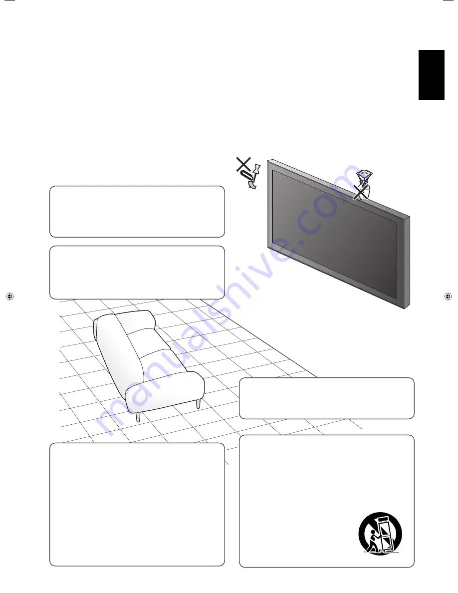
•  Never push objects of any kind into this product 

through openings as they may touch dangerous 
voltage points or short out parts that could result in a 
fi re or electric shock.

•  Never spill liquid of any kind on the product.

•  Slots and openings in the cabinet are provided for 

ventilation. These ensure reliable operation of the 
product and protect it from overheating. These 
openings must not be blocked or covered.

•  The openings should never be blocked by placing 

the product on bed, sofa, rug, or similar surface. It 
should not be placed in a built-in installation such as a 
bookcase or rack unless proper ventilation is provided 
and the manufacturer’s instructions have been 
adhered to.

•  For proper ventilation, separate the product from 

other equipment, which may prevent ventilation and 
keep distance more than 10 cm.

Unplug this product from the wall outlet and refer service to qualifi ed service personnel under the 
following conditions:

a)  When the power supply cord or plug is damaged.
b)  If liquid has been spilled, or objects have fallen on the product.
c)  If the product has been exposed to rain or water.
d)  If the product operated normally by following the operating instructions. Adjust only those controls that are covered by 

the Operation Manual, as an improper adjustment of controls may result in damage and will often require extensive work 
by a qualifi ed technician to restore the product to normal operation.

e)  If the product has been dropped or damaged in any way.
f )  When the product exhibits a distinct change in performance —this indicates a need for service.

Do not attempt to service this product yourself, as 
opening or removing covers may expose you to 
dangerous voltages and other hazards. Refer all service 
to qualifi ed service personnel.

•  Do not place this product on an unstable cart, stand, 

or table. The product may fall, causing serious injury 
to a child or adult, and serious damage to the product.

  The product should be mounted according to the 

manufacturer’s instructions, and should use a mount 
recommended by the manufacturer.

•  When the product is used on 

a cart, care should be taken to 
avoid quick stops, excessive 
force, and uneven surfaces 
which may cause the product 
and cart to overturn, damaging 
equipment or causing possible 
injury to the operator.

•  Do not use this product near water.
•  Do not use immediately after moving from a low 

temperature to high temperature, as this causes 
condensation, which may result in a fi re, electric 
shock, or other hazards.

02-05_GM-H40L1G_E-f.indd   3

02-05_GM-H40L1G_E-f.indd   3

05.10.6   1:23:59 PM

05.10.6   1:23:59 PM

Summary of Contents for GM-H40L1G

Page 1: ...SPAÑOL ENGLISH INSTRUCTIONS GM H40L1G LCD DISPLAY MONITOR BEDIENUNGSANLEITUNG LCD DISPLAYMONITOR MANUEL D INSTRUCTIONS MONITEUR LCD ISTRUZIONI SCHERMO A CRISTALLI LIQUIDI MANUAL DE INSTRUCCIONES MONITOR PANTALLA LCD LCT1943 001A ...

Page 2: ...or United Kingdom power cord only The plug on United Kingdom power cord has a built in fuse When replacing the fuse be sure to use only a correctly rated approved type re fit the fuse cover Consult your dealer or qualified personnel How to replace the fuse Open the fuse compartment with the blade screw driver and replace the fuse IMPORTANT SAFEGUARDS Electrical energy can perform many useful functio...

Page 3: ... normally by following the operating instructions Adjust only those controls that are covered by the Operation Manual as an improper adjustment of controls may result in damage and will often require extensive work by a qualified technician to restore the product to normal operation e If the product has been dropped or damaged in any way f When the product exhibits a distinct change in performance ...

Page 4: ... at doors plugs receptacles and the point where they exit from the product For added protection of this product during a lightning storm or when it is left unattended and unused for long periods of time unplug it from the wall outlet and disconnect the cable system This will prevent damage to the product due to lightning and power line surges Do not overload wall outlets extension cords or conveni...

Page 5: ...egislation By disposing of this product correctly you will help to conserve natural resources and will help prevent potential negative effects on the environment and human health which could otherwise be caused by inappropriate waste handling of this product For more information about collection point and recycling of this product please contact your local municipal office your household waste dispos...

Page 6: ...fications 39 Checking the accessories The following accessories are included with the monitor Check for them If any item is missing please contact the dealer where you have purchased the monitor Remote control RM C2005 Power cord x 1 D sub 15 pin BNC conversion cable x 1 Batteries AA R6 x 2 Ferrite cores x 2 NOTE Be sure to attach the supplied ferrite cores to the speaker cords when using external ...

Page 7: ... immediately see page 16 POWER ON button Turns on the monitor see page 16 ASPECT button Changes the aspect ratio see page 17 DISPLAY button Displays the information of the current input see page 17 5 2 3 buttons Operates the menu see page 19 OK button Enters the password for the Power on Lock see page 32 INPUT SELECT buttons Selects the input see page 16 A VIDEO button Selects the input to the VID...

Page 8: ...minals Connect external control equipment see pages 14 33 to 35 RS 232C terminal Connect to the RS 232C terminal of a personal computer For the control method using this terminal consult an authorized JVC dealer RS 485 terminals IN terminal Connect external control equipment OUT terminal Connect another component to send out the control signal coming into the IN terminal cascade connection AUDIO O...

Page 9: ...t only the L MONO terminal for monaural sound AUDIO IN B terminal STEREO terminal stereo mini jack Connect to the audio output terminals of the equipment connected to the VIDEO IN B terminal VIDEO IN A B terminals Connect video output terminals of equipment such as a VCR see page 15 VIDEO IN A terminal IN terminal BNC Connect to the video output terminals of playback equipment such as a VCR OUT te...

Page 10: ...gram below The ambient temperature of the installation place should be within the range of 0 C to 40 C slightly variable depending on ambient conditions for installation When installing the monitor near the ceiling or similar location the remote control may not work correctly because of possible effects such as reflections from the surroundings If this happens move the monitor where it is free from ...

Page 11: ...upplied ferrite cores near to the EXT SPEAKER terminals on the rear panel of the monitor CAUTION Do not short circuit 9 and speaker cords to each other Refer also to the instructions supplied with the speakers NOTE When using the external speakers set SPEAKER SELECT on the main menu to EXT external see page 23 When installing the monitor vertically Make sure to install the monitor in the direction...

Page 12: ...ace 3 VGA480 60 640 480 31 5 59 9 Non interlace 4 WVGA 60 852 480 31 5 59 9 Non interlace 5 VGA480 72 640 480 37 9 72 8 Non interlace 6 SVGA 60 800 600 37 9 60 3 Non interlace 7 XGA 60 1024 768 48 4 60 0 Non interlace 8 WXGA 60 1366 768 48 4 60 0 Non interlace 9 XGA 70 1024 768 56 5 70 1 Non interlace 10 XGA 75 1024 768 60 0 75 0 Non interlace 11 XGA 85 1024 768 68 7 85 0 Non interlace 12 XGA 75 2...

Page 13: ...ough it s frequency is within the acceptable range Depending on the connected equipment the monitor may not be compatible with composite sync Cs or G on sync signals When a preset mode signal is input the signal format is displayed on the screen For other signals the horizontal frequency and vertical frequency are displayed The DVI D terminal can accept only No 3 6 7 8 and No 13 signals When the N...

Page 14: ...e noise When unplugging a cord be sure to grasp it s plug and pull it out Refer also to the user manual of each piece of equipment Amplifier etc To stereo audio input terminals To RS 232C terminal To RS 485 output terminal To RS 485 input terminal External control input terminal of other equipment See page 33 Stereo audio cable RJ 45 cable RJ 45 cable RS 232C cable External equipment used to contro...

Page 15: ...able Stereo mini jack cable S video cable BNC cable Stereo audio cable Connect the VIDEO IN A OUT terminal to the video input terminal of another monitor etc CAUTION Since the IN terminal and OUT terminal are loop through terminals the devices connected to the OUT terminal should be correctly terminated Otherwise pictures become abnormally bright or the display screen gets affected abnormally R L P...

Page 16: ...When QUICK CHANGE is set to INPUT A B you can change Inputs A and B quickly see INPUT CONFIGURATION on page 23 Adjusting the volume From the remote control On the main unit To turn off the volume immediately Pressing the button again resumes the previous volume level When using the buttons on the main unit set MUTING to ON on the main menu see AUDIO SETTING on page 23 When the Control Lock is set t...

Page 17: ...OTE For some signals the aspect ratio cannot be changed or some modes cannot be selected When using the buttons on the main unit for changing the aspect ratio use the main menu see SIZE SETTING on page 21 Displaying the current status The information of the current input is displayed on the screen 1 When Input C D E or F is selected with an optional input card inserted the type of the card appears...

Page 18: ...modes PIP mode PBP mode Each time you press the button the corresponding dual display mode turns on or off When the dual display mode is activated the current input is displayed on the main window and the other is displayed on the sub window NOTE The dual display mode is available only when analog RGB signals are being input to Input B For details see page 25 You cannot change the input when the du...

Page 19: ... displayed 3 Press 5 to select an item then press 2 3 to make adjustments 4 Press MENU EXIT to return to the previous menu Pressing the button again exits the menu operation NOTE For some items adjustments will be made by pressing 2 3 in step 2 MENU EXIT SET UP 5 2 3 MENU Works in the same way as MENU EXIT on the remote control SET UP On the main unit 5 Works in the same way as 2 3 on the remote c...

Page 20: ...he n NO then MENU reset key key 01 BRIGHT 01 CHROMA 01 PHASE 01 BACK LIGHT HI G H COLOR TEM P 01 SHARPNESS Are yo u sure YES th en NO the n MENU res et key key ENGLI SH MENU MEN U Menu Configuration MAIN MENU On the main menu you can make various adjustments and settings for picture screen and audio Select the menu language English German French or Russian Configuration of the main menu screen NOTE ...

Page 21: ...0 Hz 60 Hz You can make the detailed settings of the color temperature using the set up menu see COLOR TEMP on page 27 SIZE SETTING Item To do Setting value H SIZE Adjusts the horizontal screen size Varies depending on other settings H POSITION Adjusts the horizontal screen position V SIZE Adjusts the vertical screen size V POSITION Adjusts the vertical screen position DOT CLOCK Adjusts to elimina...

Page 22: ...en MENU res et key key Are you sure YES th en NO the n MENU re set key key PIC TU RE S ETTIN G SIZE SE TTI NG AUD IO SE TTI NG INP UT C O NFI GUR ATI ON F UN CTI O N SETTI NG L AN G UAG E MAI N ME NU EN GLI SH MENU ME NU 22 MenuConfiguration MAINMENU cont Select the menu language English German French or Russian Configuration of the main menu screen 1 1 When no HD SD SDI or SDI input card option is ...

Page 23: ...100 white W 50 half transparent BAR BRIGHTNESS Selects the brightness of the audio level meter display HIGH LOW REFERENCE LEVEL Sets the standard input level 20dB 18dB OVER LEVEL Sets the input level s lower limit indicated in red for the 3COLORS display 10dB 8dB 6dB 4dB 2dB reset Restores the default setting for LEVEL METER SETTING reset Restores the default setting for all the items in AUDIO SET...

Page 24: ...re you s ure YES then NO the n MEN U re set key key MULT I SIZ E MULT I POSI reset MULTI DISPL AY 2 2 1 P IC TU RE S ETTIN G S IZE SE TTI NG AUD IO SE TTI NG INP UT C O NFI GUR ATI ON FUN CTI O N SETTI NG LA N G UAG E MAI N ME NU ENG LI SH MENU ME N U MenuConfiguration MAINMENU cont Select the menu language English German French or Russian Configuration of the main menu screen When MODE is PBP When ...

Page 25: ...RIGHT 1 CENTER LEFT 1 LEFT 2 reset Restores the default setting for DUAL DISPLAY STATUS DISPLAY Sets if you want the information of the current input to be displayed on the screen see Displaying the current status on page 17 OFF ON 1080 1035 Selects a High Definition signal type 1080 60i or 1035 60i for the component signal to view the picture correctly 1080 1035 SUB HOUR METER Displays the hours o...

Page 26: ... PORT F 5 res et RJ 4 5 I R OUT MAKE I NP A I NP C POW E R ASPECT Are yo u sure YES the n NO then MENU reset key key Are yo u sure YES the n NO then MENU reset key key 000 B DRIVE 000 G DRIVE 000 R DRIVE 00 0 B CUT OFF 000 G CUT OFF 000 R CUT OFF MENU ME N U MENU 26 Menu Configuration SET UP MENU On the set up menu you can change various settings such as color temperature and timer Configuration of ...

Page 27: ... after signals stops being input 5s 1min 30min reset Restores the default setting for all the items in NO SYNC FUNCTION REMOTE SYSTEM Item To do Setting value REMOTE IN SEL Selects the input terminal used for external control D sub9 RJ 45 CNT RJ45 OUT Selects the external control method for RS 485 OUT terminal RS485 IR OUT CNT RJ45 IN Selects the external control method for RS 485 IN terminal RS48...

Page 28: ...IME res et SET UP ME NU TIMER 1 2 CO N TRO L L OC K P OW ER O N D ELAY S Y NC TER M FAN S PEE D I P MO D E S A M PL IN G MODE rese t all r e se t M O DE L V E R SET UP ME NU 2 2 14 25 O N 08 16 O N 21 20 O FF FAS T H I GH H I GH M ODE 1 STD G M H 40L1G A T IMER PRESENT TIME HOURS MINUTES 1 4 25 1 4 2 5 T IMER POWER ON TIME HOURS MINUTES 0 8 16 0 8 1 6 T IMER POWER OFF TIME HOURS MINUTES 2 1 20 2 1...

Page 29: ...u cannot operate the monitor with the buttons on the main unit Setting value ON OFF NOTE You can use the remote control and external control while the control lock is set To release the lock use the remote control POWER ON DELAY Sets the time when the power supply to the monitor s circuits excluding the micro computers starts after the power button is pressed Setting value OFF FAST SLOW NOTE If yo...

Page 30: ...buttons for each operation Page CO L O R TEMP NO SY NC FUN CTI ON RE M OTE S YS TE M P OW ER O N LOCK TIM E R V CR ADJ 00 SET UP ME NU 1 2 CO N TRO L L OC K P OW ER O N D ELAY S Y NC TER M FAN S PEE D I P MO D E S A M PL IN G MODE rese t all r e se t M O DE L V E R SET UP ME NU 2 2 O FF FA ST H I GH H I GH M OD E1 S TD G M H40L1G A A re yo u su re YES the n NO then ME NU re se t key key A re yo u ...

Page 31: ...play thin vertical lines of the picture more clearly Select STD for VGA480 60 or XGA 60 and WIDE for WVGA 60 or WXGA 60 This item is not displayed for other signals Setting value STD WIDE reset Restores the default setting for all the items in the set up menu all reset Restores the default setting for all the items in the main menu and set up menu except the use time HOUR METER The power is turned...

Page 32: ...SS ID SETTING on the POWER ON LOCK sub menu of the set up menu 2 Enter a password See How to enter a password below 3 Press OK The cursor moves to the second line 4 Enter the password again for confirmation then press OK If the password is different from the one entered in step 2 PASS ID NG appears and the POWER ON LOCK sub menu is displayed In this case repeat from step 1 7 To activate the Power on...

Page 33: ...erial communication RJ 45 RS485 RS485 D sub9 RS485 Any IR OUT system Any IR OUT Any MAKE system RJ 45 RS485 MAKE TRIG system RJ 45 RS485 TRIG For the monitor connected to the external control equipment set REMOTE IN SEL according to the actual connection Set other monitors by following the setting of the serial communication with REMOTE IN SEL set to RJ 45 in the table above NOTE Control priority ...

Page 34: ...ble below Baud Rate 4800 9600 19200 factory pre set 4800 Data Bits 8 bits Parity No parity Stop Bits 1 bit Communication Cord ASCII Cord RS 232C Prepare a straight cable with a RS 232C connector RS 485 terminal This is a female terminal Pin No IN terminal signal OUT terminal signal 1 TXD TXD 2 TXD TXD 3 RXD RXD 4 NC NC 5 NC IR OUT 6 RXD RXD 7 5 V power NC 8 GND GND The 5V power supply of the 7th t...

Page 35: ...nvalid Valid PBP Turns on off the PBP mode see page 18 Invalid Valid No function NOTE You cannot assign the same function to different pin terminals The TRIG trigger system switches each function by short circuiting for approx 1 second Operation 1 Short circuit the 6th pin terminal External control to the 8th pin terminal GND so that the monitor can be controlled by the external control 2 Set CNT RJ...

Page 36: ... Is the power cord connected see page 15 Is the main power switch POWER turned on see page 16 The remote control does not work Are the batteries installed correctly see page 6 Are the batteries exhausted Is the front end of the remote control pointing toward the remote sensor Is there any object blocking the path between the remote control and the remote sensor Is the monitor too far away from you...

Page 37: ...disappears quickly When INPUT B of INPUT CONFIGURATION is set to COMPONENT with a personal computer connected to the RGB COMPO terminal the menu operation is not available Select another input to operate the menu 23 Some items are not shown on the menu Items not available for the current input signal are not displayed Change the input or signal format Some items are displayed only when the corresp...

Page 38: ...ER still flashes this problem may be caused by improper installation or improper location of the monitor In this case consult your dealer immediately to solve this improper installation and to improve the circumstances around the monitor If TEMP OVER appears in red TEMP OVER will be shown for about two minutes the monitor will shut off automatically then the self diagnostic lamps light in red If thi...

Page 39: ...for installation Input output terminals VIDEO IN A Video input BNC terminal x 1 1 V p p 75 Ω Y C terminal x 1 Y 1 V p p 75 Ω C BURST 0 286 V p p 75 Ω for NTSC 0 3 V p p 75 Ω except for NTSC Video output BNC terminal x 1 1 V p p 75 Ω VIDEO IN B RGB COMPONENT input D sub 3 row 15 pin x 1 RGB is compatible with DDC2B Video signal G Y 1 V p p 75 Ω including sync B R PB CB PR CR 0 7 V p p 75 Ω Horizont...

Page 40: ...itted or composed and may be more or less different from actual products Design and specifications are subject to change without notice IBM and IBM PC are registered trademarks of International Business Machines Corporation Macintosh is registered trademarks of Apple Computer Inc All other product names mentioned herein are used for identification purposes only and may be the trademarks or registered...

Page 41: ... 2005 Victor Company of Japan Limited 1005MKH MW VP ...

Reviews: