background image

(No.PA019)1-11

2.7.4 Setting items

Item

Initial value

Adjustment 

range

Description

Setting 

object

‹

Software version

Software version

------

------

Information of PROGRAM

------

‹

Option

Back color

Blue

[Select 2 items] "Sets no signal background color to blue or black.

[Blue] : Blue color [Black] :Black color"

Common

Auto shutdown

ON

[Select 2 items] If POWER OFF is selected, no warning will be displayed on and

after 1900 hours of the lamp operating time. However, POWER

ON is also available after 2000 hours of the lamp operating time.

Common

Color temp

D65

Select 3 items Setting of [D65]:6500K, USER1, USER2

Common

R

0

-255~0

Setting color temp of red

Common

G

0

-255~0

Setting color temp of green

Common

B

0

-255~0

Setting color temp of blue

Common

Factory reset

------

------

Press [ENTER] then all reset.

Common

Adjust pattern

------

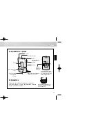
[Select 5 items] Press [ENTER] then Test pattern appear. (Refer to following Fig.1) Common

Test patter Screen

(When the      key is pressed, the screen is changed one after the other as shown in the above.)

SERVICE MENU Screen

convergence


checker

cross-hatch

software version

software version

Back Color


Black

Auto shut off


Off

Color temp.


Blue

On

USER1 

D65 

USER2

Factory reset

ENTER


options

options

RED


GREEN

BLUE

0

0

0


Adjust pattern

ENTER

Summary of Contents for DLA-HD2KU - D-ila Projector Head

Page 1: ...No PA019 2004 10 HOME THEATER PROJECTOR PA019 2004 10 DLA HD2KU DLA HD2KE TABLE OF CONTENTS 1 PRECAUTION 1 3 2 SPECIFIC SERVICE INSTRUCTIONS 1 7 3 DISASSEMBLY 1 13 4 ADJUSTMENT 1 18 5 TROUBLESHOOTING 1 31 ON ENTER OFF FOCUS TEST MENU EXIT PRESET HIDE LIGHT OPERATE ...

Page 2: ...le 5m 1 Power code 2 5m 1 Projection system D ILA device D ILA reflective activematrix principle system 0 82 inch 2 1cm measured diagonally H 1920 pixels V 1080 pixels 3 Total 6 220 000 pixels Projection lens 1 3times 1 8 1 2 35 1 manual ZOOM lens 50 fix shift Screen size 40 101 6cm tele min 200 508cm recommended measured diagonally with aspect 16 9 Projection distance approx 1 5m 4 92ft 12m 39 36...

Page 3: ... 9 When a power cord has been replaced check that 10 15 kg of force in any direction will not loosen it Fig 1 1 2 10 Also check areas surrounding repaired locations 11 Products using cathode ray tubes CRTs In regard to such products the cathode ray tubes themselves the high volt age circuits and related circuits are specified for compli ance with recognized codes pertaining to X ray emission Conse...

Page 4: ...lug prongs and externally ex posed accessible parts Use an AC voltmeter to measure across both terminals of load Z See Fig 1 1 9 and follow ing Fig 1 1 12 Fig 1 1 9 5 Grounding Class 1 model only Confirm specified or lower grounding impedance between earth pin in AC inlet and externally exposed accessible parts Video in Video out Audio in Audio out or Fixing screw etc Measuring Method Connect mill...

Page 5: ...ts high heat and contains high pressure during use If touched the lamp bulb may rupture and burns may result Before attempting to replace the lamp remove the power cord plug from the outlet and wait for the lamp bulb to cool at least one hour Then proceed to replace the lamp Bottom chassis WARNING High voltage Never open any cover on the projector except the lamp and filter covers Dangerous electr...

Page 6: ...y of free space between the projector and adjacent walls ceiling and other equipment Note that excess heat can cause failure and damage to both the projector and nearby equipment Required spacing Front 15cm left and right sides 30cm rear 50cm When the unit is enclosed with block according to the required spacing on the left side provide the unit with adequate ventilation so that the temperature in...

Page 7: ...mperature abnormally high shift to emergency mode Extinguished Internal temperature normal Lighted Lamp replacement time near used approx 1900 hours At power on message appears by the on screen display for advising to LAMP REPLACE Flashing Lamp end of life approx 2000 hours power on inhibited Extinguished Mode other than above lamp abnormally absent TOP VIEW Operation Panel TOP VIEW Operation Pane...

Page 8: ... of time 30 minutes to 1 hour to cool before proceed ing The lamp can break if dropped or subjected to physical shock Use care not to directly touch or soil the lamp projecting glass face When installing the lamp unit observe the interior projections of the lamp cover are securely inserted into the holes of the projector Since the lamp cover projections engage the inter lock switch part of the pro...

Page 9: ... 4 CONNECTION AND OPERATION CAUTIONS The projector can function with fH 56 25kHz 67 43kHz 67 5kHz fV 50Hz 59 94Hz 60Hz signal input but even within this range partial picture loss fold over at the top and bottom picture edges and other effects can occur according to signal type and conditions to prevent a normal projected image see Input Sync Frequency of the OPERATING INSTRUCTION 2 5 SERVICE POLI...

Page 10: ...choosing the SET TING MENU the cursor will shift to the SETTING AD JUSTMENT ITEMS of each SETTING MENU 3 When the cursor is shifted choose the SETTING AD JUSTMENT ITEMS with the button 4 Using the button change the setup values and ad justment values respectively 5 When the EXIT button is pressed the cursor will return to the SETTING MENU 6 When the MENU button is pressed the SERVICE MENU will go ...

Page 11: ...e Common Color temp D65 Select 3 items Setting of D65 6500K USER1 USER2 Common R 0 255 0 Setting color temp of red Common G 0 255 0 Setting color temp of green Common B 0 255 0 Setting color temp of blue Common Factory reset Press ENTER then all reset Common Adjust pattern Select 5 items Press ENTER then Test pattern appear Refer to following Fig 1 Common Test patter Screen When the key is pressed...

Page 12: ...Color temp Color temp RED GREEN BLUE Test pattern Menu Position Mask Source 2 2 D65 0 0 0 CENTER Off 60p Position Item Position ENTER ENTER This adjustment is only available when the USER is selected for color temperature Menu display Flip H Flip V Picture Shift Sleep time RS232C bps 15sec Off Off 0 Off 19200 Lamp time Lamp usage time MENU Options Information Set up ...
Page 13: ... screws marked C on the right side of the main frame Fig 2 2 Remove the 3 screws marked D on the left side of the main frame Fig 2 3 Remove the 1 screw marked E on the rear side of the main frame Fig 2 4 Remove the harness from the connector CN701 of the CONTROL UNIT which is secured to the back of the TOP COVER 5 Lift up the TOP COVER to remove it 3 4 PROTECT COVER Remove the LENS COVER Remove th...

Page 14: ... the TERMINAL BOARD Fig 3 2 Remove the TERMINAL BOARD 3 Using a nut driver and the like remove the 4 screws marked H fixing the D SUB connector and DVI connector Fig 3 4 Pull out the SHIELD SHEET toward you to remove it 1 After 2 in the procedure above the TERMINAL BOARD and the SHIELD SHEET can be replaced However be careful about the cord wire and the harness that are not replaced 3 8 MAIN PWB A...

Page 15: ...ET 1 Remove the 5 screws marked N fixing the POWER SUP PLY SHIELD CASE 1 Fig 4 2 Disconnect the connectors CN1 and CN2 3 Remove the 1 screw marked O fixing the LAMP POWER SUPPLY CORD SUPPRESSION BRACKET Fig 4 4 Lift up the LAMP POWER SUPPLY CORD SUPPRES SION BRACKET to remove it and remove the LAMP POWER SUPPLY CORD 5 After setting up the POWER SUPPLY SHIELD CASE 1 remove the 4 claws marked a whic...

Page 16: ... CN005 of the POWER SUPPLY PWB ASS Y Fig 5 3 13 POWER SUPPLY SHIELD CASE 2 RADIATION FAN INTERLOCK SWITCH COOLING FAN1 DUCT1 Remove the LENS COVER Remove the LAMP UNIT Remove the TOP COVER Remove the MAIN PWB ASS Y Remove the POWER SUPPLY SHIELD CASE 1 Remove the POWER SUPPLY PWB ASS Y 1 Remove the 4 screws marked Q fixing the POWER SUP PLY SHIELD CASE 2 Fig 5 2 Lift up the POWER SUPPLY SHIELD CAS...

Page 17: ...emove the LENS COVER Remove the LAMP UNIT Remove the TOP COVER Remove the MAIN PWB ASS Y Remove the PROTECT COVER Remove the OPTICAL BLOCK for easier operation 1 Remove the 3 screws w fixing the DD SUB1 PWB ASS Y Fig 6 2 Remove the cord wire from the connectors CN007 CN008 and CN009 3 17 COOLING FAN2 DUCT2 COOLING FAN3 DUCT3 DUCT4 Remove the LENS COVER Remove the LAMP UNIT COVER Remove the TOP COV...

Page 18: ... device for example HAMAMAT SU PHOTONICS S1226 8BK Phototransistor or CdS photoconductor with amplifier Color filters G color filter ex MELLES GRIOT 03 FIV 044 R color filter ex MELLES GRIOT 03 FIB 014 B color filter ex MELLES GRIOT 03 FIV 028 Screen Darkroom illumination less than 0 03 lx Use these instruments and tools if necessary NTSC PAL signal generator composite output Y C output Gray scale...

Page 19: ...ed data will be downloaded in the order of EEPROM EEPROM2 SUB EEPROM 5 When the download has completed Save Data with File Name dialog box will be displayed Then save the data with a file name z DATA ENTRY 1 Enter Stand by mode and open the PSA controller on the PC 2 Click System in the main menu When the pull down menu is displayed click Backup ROM Data and open ROM Data Up Load Down Load 3 Tick ...

Page 20: ...ss Receive All at the top right of the screen 6 Press R at the top left of the screen Set the following buttons located in the furthest right of the screen as follows Set GINDAT SUPDAT DCSDAT to ON and the rest to OFF Refer to Fig 2 Fig 2 7 In the DDIC Control EVR tag screen set the value for DC_R DC_G and DC_B to 90 respectively Refer to Fig 2 8 Put the photo sensor at 40 cm away from the surface...

Page 21: ...2 and the rest to 0 respectively Refer to Fig 3 Fig 3 10 In the DDIC Control EVR tag find the point by sliding a CC slider CC_R for red CC_G for green and CC_B for blue where the photo sensor waveform becomes minimum Refer to Fig 4 Fig 4 11 Perform the above procedures 9 and 10 for all colors R G and B 9 Enter 512 Adjust here ...

Page 22: ... 40cm away from the projector lens surface Screen center and turn the CL200 to ON MEASUREMENT 9 Open the Gamma adjustment file and click CONNECT in the DC sheet 10 Click MEASURE when OK is shown Refer to Fig 3 Fig 3 11 When the measurement is completed click CONNECT in step 10 to disconnect the system Boot the PSA software to connect the PC and the Projector 12 On completion of the measurement ent...

Page 23: ...opriate file name 5 Connect the PSA and click Gamma on the PSA screen 6 Click CUSTOM on the Gamma correction screen Refer to Fig 2 7 Right click on the Gamma curve in the Gamma Correction screen to select Load CUSTOM Data and then select the file saved in step 3 8 Click RGB Transmit All on the Gamma correction screen Refer to Fig 2 Fig 2 9 Click DDIC in the SPA menu and set GAMDAT to ON as shown i...

Page 24: ...r the BK16 cell in the sheet and save it with an appropriate file name 18 Perform the procedures in step 5 6 7 and 8 Please note the file to be loaded is the one that is saved in step 17 19 Select the R button in the Gamma correction screen Refer to Fig 4 20 Right click on the Gamma curve in the Gamma correction screen to select Copy Gamma Data Refer to Fig 4 Fig 4 21 Select Gamma2 2 in the Gamma ...

Page 25: ...22 23 and 24 to paste these to Gamma1 8 27 Perform the same procedures as steps 25 and 26 and create the data for Gamma2 6 in Gamma2 6 28 In CUSTOM the same data as Gamma2 2 are to be input To do this right click on the Gamma curve in the Gamma correection Gama2 2 screen Select Make CUSTOM Data then Gamma2 2 to allow the Gamma2 2 data to be input to CUSTOM 29 Save the Gamma adjustment file and clo...

Page 26: ...rded value 11 Open Menu DDIC Gain Setup and click Gain Adjust DDIC GAIN so that the brightness of the screen at the R Flat Field level of 614 become the same value re corded in 8 above 12 In the same manner as for the above steps also adjust G and B Flat Field level 13 Adjust LUM if necessary Keep the Flat Field level at 1023 at the center of the screen as much as you can 14 After adjustment trans...

Page 27: ... all buttons located at the furthest right of the screen set RVSDAT to ON and the rest to OFF Refer to Fig 2 8 Repeat the procedure in step 7 for the G and B buttons 9 Click the EVR tag in the DDIC Control screen 10 Set the values for DC_R DC_G DC_B to 90 Refer to Fig 3 Fig 3 11 Press the Load File button in the Register tag in the DDIC Control screen 12 Select PHS_RGBch_Inter Phase Deviation_Clea...

Page 28: ...gital Voltmeter without a minus sign to FORWARD ROTATION White 1 or the C3 cell in the Excel file Refer to Fig 4 12 Connect the probe to the 2nd Phase pin and enter the measured value to C4 Repeat the procedure through to the 16th phase 13 Set the slide switch on the Phase Measurement circuit to REVERSE 14 Connect the Phase Deviation Measurement circuit probe to the 1st phase pin a header pin on t...

Page 29: ...n the remote control unit to display the grey scale of R Color to be adjusted 8 Using the DDIC Control EVR tab adjust R_DELAY_CTL Refer to Fig 2 to allow the reflection to be minimum 9 Perform the procedures in steps 7 and 8 for G and B 10 When the procedure in step 9 is completed click 50P in the EVR tab and then click Receive All 11 Perform the procedures in items 7 8 and 9 Fig 3 Fig 4 Instrumen...

Page 30: ...ss the DDIC button This causes the DDIC Control screen to be displayed Subsequent works are to be performed on this screen 4 Press the Receive All button at the top right of the screen 5 Set R_MUTE G_MUTE and B_MUTE to ON with the FPGA tab 6 Set Flat Field Level of R G and B to all 0 All black ADJUSTMENT 1 Move the slider of GK_R GK_G and GK_B with the EVR tab to allow the picture frame to be dark...

Page 31: ...int Function Thermal sensor Thermostat Lamp unit Optical block Lamp section 140 C AC line one side open Thermal sensor IC Set interior Lamp area MAIN PWB ASS Y IC728 70 C Power off by main CPU emergency mode Thermal sensor IC Set exterior Filter area MAIN PWB ASS Y IC727 62 C Power off by main CPU emergency mode Motor operation detection circuit Cooling fan Cooling fan interior Fan stop Power off ...

Page 32: ...ideo process circuit failure 6 Video system data initializing error Again supply power press OPERATE button OK Operating loading error 7 Internal temperature abnormally high Avoid obstructing ventilation openings intake and exhaust OK Circuit error or other fault NG Replace MAIN PWB ASS Y OK Defective sensor and detection circuit 8 Out side temperature abnormally high Ambient temperature of the un...

Page 33: ... Internal temperature detected by sensor dur ing error event Error cord Detected condition Indicated LED E01 Lamp can not light during shift from stand by to operation mode STAND BY LAMP Blinking E02 Lamp use time exceeds 2000h LAMP Blinking E03 Inter IC bus communication error ACK receive error Absent E06 Lamp extinguishes during projection OPERATE LAMP Blinking E07 Cooling fan stops fan lock All...

Page 34: ... No PA019 ILA CENTER 12 3 chome Moriya cho kanagawa ku Yokohama kanagawa prefecture 221 8528 Japan VICTOR COMPANY OF JAPAN LIMITED VPT Printed in Japan ...

Reviews: