background image

Retrieving an adjustment data

1

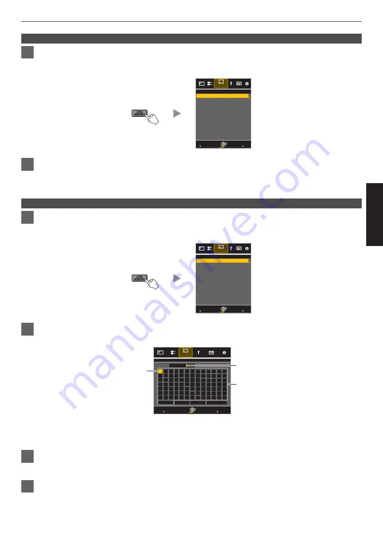
Press the [LENS MEMORY] button to display “Lens Memory Select”

0

You can also press the [MENU] button to display the menu followed by selecting “Installation”

"

“Lens

Control”

"

“Lens Memory Select”.

.

MENU

BACK

-----

-----

-----

MEMORY2

-----

-----

-----

-----

-----

>>

MEMORY1

Back

Operate

Select

Exit

Lens Memory Select

Installation

2

Select the adjustment data to retrieve, and press the [OK] button

0

The retrieved data is adjusted automatically.

0

If no adjustment data has been saved, the item will be grayed out and cannot be selected.

Renaming an adjustment data

1

Press the [LENS MEMORY] button three times to display “Lens Memory Name Edit”

0

You can also press the [MENU] button to display the menu followed by selecting “Installation”

"

“Lens

Control”

"

“Lens Memory Name Edit”.

.

MENU

BACK

-----

-----

-----

MEMORY2

-----

-----

-----

-----

-----

>>

MEMORY1

Lens Memory Name Edit

Back

Operate

Select

Exit

Installation

2

Select the adjustment data to edit, and press the [OK] button

0

An edit screen appears.

.

MENU

>>

MEMORY1

}

?

.

y

l

Y

L

{

=

,

x

k

X

K

]

/

0

w

j

W

J

[

-

9

v

i

V

I

>

+

8

y

h

U

H

<

*

7

t

g

T

G

)

&

6

s

f

S

F

(

%

5

r

e

R

E

~

$

4

q

d

Q

D

|

#

3

p

c

P

C

;

"

2

o

b

O

B

\

^

z

M

Z

m

@

:

!

1

n

a

N

A

SPACE

OK

All Clear

Clear

Name

Character List

Selection Cursor

Input Cursor

BACK

Back

Operate

Select

Exit

Lens Memory Name Edit

Installation

0

You can input up to 10 characters.

0

Characters that are usable include alphabets (upper or lower case), numeric characters, and symbols.

0

Pressing the [Back] button cancels the content that is currently being edited, and exits the edit mode.

3

After renaming, select “OK” and press the [OK] button

0

A message prompting you to confirm the change appears. Selecting “Yes” changes the data name.

4

Press the [MENU] button to exit

21

Operate

Summary of Contents for DB-HDR36

Page 1: ...Garder cetteinformation comme référence pour le futur Instrucción para el cliente Introduzca a continuación el nº de serie que aparece en la parte inferior lateral de la caja Conserve esta información como referencia para uso ulterior For Customer use Enter below the serial No which is located on the side of the cabinet Retain this information for future reference LY HDR36 LY HDR36 LY HDR36 Model ...

Page 2: ...vide reasonable protec tion against harmful interference in a residential installation This equipment generates uses and can radiate radio frequency energy and if not installed and used in accordance with the instruc tions may cause harmful interference to radio communications However there is no guarantee that interference will not occur in a particular installation If this equipment does cause h...

Page 3: ...If the product has been exposed to rain or water If the product does not operate normally by following the operating instructions Adjust only those controls that are covered by the Operation Manual as an improper adjustment of controls may result in damage and will often require extensive work by a qualified technician to restore the product to normal operation If the product has been dropped or d...

Page 4: ... during use please be careful in regard to the ambient temperature of the unit If you use a central heating the temperature close to the ceiling will be higher than normally expected Video images can burn into the electronic com ponent parts Please do not display screens with still images of high brightness or high contrast such as found in video games and computer programs Over a long period of t...

Page 5: ...lectromagnetic compatibility and electrical safety European representative of JVC KENWOOD Corporation is JVCKENWOOD Deutschland GmbH Konrad Adenauer Allee 1 11 61118 Bad Vilbel GERMANY INFORMATION Manufacturer JVC KENWOOD Corporation 3 12 Moriya cho Kanagawa ku Yokohama shi Kanagawa 221 0022 JAPAN Importer EU only JVC KENWOOD U K Limited 12 Priestley Way London NW2 7BA UNITED KINGDOM For more deta...

Page 6: ...cette pile contient du plomb Informatie voor gebruikers over het verwijderen van oude apparatuur en batterijen Alleen Europese Unie Deze symbolen geven aan dat appara tuur met dit symbool niet mag worden weggegooid als algemeen huishoudelijk afval Als u het product of de batterij wilt weggooien kun t u inzamelsystemen of faciliteiten voor een geschikte recycling gebruiken Opmerking Het teken Pb on...

Page 7: ...t light source do not stare into the beam RG2 IEC 62471 5 2015 Location information of the labels The warning label shown in the above diagram is sticked on the bottom of the projector inside this unit 7 Getting Started ...

Page 8: ...Size Aspect 22 Adjust Set Adjusting the Image Quality 23 Setting the Picture Mode 23 Adjusting to the Preferred Color Color Management 24 Adjusting the Output Value of the Projected Image Gamma 25 Fine tuning to the Preferred Gamma Setting 25 Reducing the After image of Fast moving Images Blur Reduction 27 Adjusting the Contrast Lens Aperture 28 Correcting Uneven Illumination Uniformity Correction...

Page 9: ...ions are for image display equipment in general items not applicable to this unit are also included Optional Accessories 0 Replacement lamp Product no PK L2615U 0 HDR rear projection screen Product no SF HDR36G2 SF HDR36N2 SF HDR36G4 SF HDR36N4 SF HDR36G10 Screen Gain Screen Type Glossy Matte 2 4 SF HDR36G2 SF HDR36N2 4 8 SF HDR36G4 SF HDR36N4 10 SF HDR36G10 0 HDR rear projection stand Product no ...

Page 10: ...r to cool down the internal temperature Do not block or prevent the outflow of hot air Doing so may cause the unit to malfunction C Feet D Front Panel Main Unit Side E E Handles There are two handles on each side Be sure to carry this unit using the handles when moving the unit 10 Getting Started ...

Page 11: ...unit are run through the holes to the outside of the unit Up to five cables including the power cord HDMI cable x2 LAN cable and RS 232C cable H Through holes for Fall Prevention Wire at the bottom side You are recommended to attach a commercially available fall prevention wire to the unit to prevent it from falling in the event of an earthquake etc Use these holes to attach the wire 11 Getting St...

Page 12: ... restores the original brightness P 44 M LIGHT Illuminates the buttons on the remote control N JKH I keys For selecting an item O OK Confirms a selected item P MENU Displays the menu or hides the menu if it is displayed Q BACK Returns to the previous menu R PICTURE MODE Switches the Picture mode to DYNAMIC SRGB DCI or USER1 to USER6 P 23 S GAMMA For setting the gamma level P 25 T COLOR TEMP For se...

Page 13: ...l CAUTION 0 Do not put the remote control in a place with an exposure to direct sun light or high temperature It may deformed due to heat or the internal components may be adversely affected resulting in fire hazard 0 Remove the batteries from the remote control when storing the remote control Storing the remote control for a prolonged period without removing the batteries can cause battery leakag...

Page 14: ...n dark images or dull colors Dirt that sticks to the optical components cannot be removed Maintain clearance from the wall etc As the unit discharges a large amount of heat install it with adequate clearance from the surroundings as shown below 200 mm and above 100 mm and above It is not necessary to keep clearance at the sides Exhaust Vent Air Inlets Using the projector You are recommended to att...

Page 15: ...lifier or speaker The actual cable connection may differ from the cable connection illustrated in the diagram depending on the condition of the default setting Connecting to the HDMI Input Terminal Digital Input Connecting via HDMI cable HDMI Output Terminal Laptop etc HDMI Cable Sold Separately Rear Panel of Main Unit 0 If noise occurs move the laptop away from this unit Connecting via an HDMI ad...

Page 16: ...the length of the cable or lower the resolution of the video transmitting equipment Connecting to the LAN Terminal Desktop PC etc Server Hub Network LAN Cable Sold Separately Rear Panel of Main Unit 0 The network is used to control this unit It is not used for sending or receiving video signals 0 Please contact your network administrator for information concerning the network connection 0 For more...

Page 17: ... power consumption of this unit is large Please connect it directly to the wall outlet 0 When you are not using the projector please unplug the power cord from the outlet 0 If the use of an extension cord is necessary use a cord with a current rating higher than that of the power cord of this unit The current rating of the power cord of this unit is 10 A 0 The power supply voltage is AC 100 V to 2...

Page 18: ...u sure you want to turn off message is displayed press the B STAND BY button again CAUTION 0 The power cannot be turned off within approximately 60 seconds after it has been turned on 0 After the light goes off the fan will run for about 100 seconds to cool down the lamp Cool down mode Do not disconnect the power cable while cooling is in progress 0 The power cannot be turned on again while coolin...

Page 19: ...On P 36 ABCD ABCD ABCD Shift Screen Position Adjustment Zoom Screen Size Adjustment Focus Adjustment 2 Use the JKH I keys to adjust Focus Zoom screen size and Shift screen position 0 Use the JK keys to adjust Focus and Zoom screen size and the JKH I keys to adjust Shift screen position 3 Press the MENU button once or the BACK button four times to end adjustment INPUT PICTURE MODE INFO HIDE DYNAMIC...

Page 20: ...ACK Back Operate Select Exit Lens Memory Save Installation 3 Select the item to save and press the OK button 0 A message prompting you to confirm the saving of the adjustment data appears Selecting Yes saves the adjustment data 0 Prior to saving the adjustment data a message prompting you to rename the adjustment data to be saved appears Selecting Yes allows you to rename the data P 21 0 Items wit...

Page 21: ... Control Lens Memory Name Edit MENU BACK MEMORY2 MEMORY1 Lens Memory Name Edit Back Operate Select Exit Installation 2 Select the adjustment data to edit and press the OK button 0 An edit screen appears MENU MEMORY1 y l Y L x k X K 0 w j W J 9 v i V I 8 y h U H 7 t g T G 6 s f S F 5 r e R E 4 q d Q D 3 p c P C 2 o b O B z M Z m 1 n a N A SPACE OK All Clear Clear Name Character List Selection Curso...

Page 22: ... the screen size to 16 9 For SD signals the two sides are expanded Zoom Enlarges the entire image Not selectable in the case of HD signals Auto Positions the image at the center with the entire image enlarged Displayed only during PC signal input Just Displays the input image in the actual size Full Fills the entire screen with the image with the size aspect of the input image ignored 0 This item ...

Page 23: ...GB REC709 Picture mode that has been set to sRGB REC709 standard DCI DCI 1 Picture mode with the color space set to DCI P3 and the gamma set to 2 2 USER1 to USER6 User 1 to User 6 2 Enables user defined image quality data to be saved and retrieved 1 DCI is the abbreviation for Digital Cinema Initiatives 2 The color gamut gamma and color temperature can be configured using a calibration software op...

Page 24: ... Setting Range Description Axis Position 30 to 30 Fine tune the position of the central axis of the selected color Hue 30 to 30 Adjusts the hue color tone Saturation 30 to 30 Adjusts the color saturation vividness 30 dull to 30 vivid Brightness 30 to 30 Adjusts the brightness 30 dark to 30 bright 0 Selecting Reset resets all the adjustment data 0 Pressing the HIDE button on the remote control enab...

Page 25: ... Bright Level Dark Level Picture Tone Color Selection Correction Value Gamma Picture Adjust Gamma 2 Adjust to the preferred setting Item Description Setting Correction Value For selecting a gamma setting as the adjustment origin 1 0 1 8 2 0 2 2 2 4 2 6 3 0 Import 1 Import 2 Import 3 Color Selection For selecting the color for adjusting Picture Tone Dark Level and Bright Level White Red Green Blue ...

Page 26: ...e Normal setting 0 You can use the calibration software sold separately to customize the gamma data adjustment and import the created gamma data Please check with your authorized dealer for details Gamma Adjustment 0 When the gamma curve is a straight line The brightness and contrast of the video input will be the same as that of the video output 0 Area for which the gamma curve is above the strai...

Page 27: ...nd select Picture Adjust Blur Reduction Clear Motion Drive Setting Description Off Interpolation is not performed On Softens the image quality 2 Press the MENU button to exit Motion Enhance Optimal image quality with reduced image blurring is made possible by enhancing the responsiveness of the liquid crystal device If the image outline is unnatural set this item to Off 1 Press the MENU button to ...

Page 28: ...ing to your preference 1 Pressthe MENU buttontodisplaythemenu select PictureAdjust PictureMode to select the picture mode to be adjusted 2 Select Lens Aperture and use the H I keys to move the slider to adjust the lens aperture 3 Press the MENU button to exit 28 Adjust Set ...

Page 29: ...ormity Correction and set to On 2 Select Gain Adjustment and Viewing Position to adjust the extent of uniformity correction and the viewing position respectively Gain Adjustment For setting the extent of uniformity correction Increasing the correction value further corrects the brightness degradation at the periphery The correction value varies depending on the screen type and viewing distance Set...

Page 30: ...p Power P 32 9 Lens Aperture P 32 9 User Name Edit P 32 I Color Management P 32 I Color Temp P 33 9 Correction Value P 33 9 Gain Red Gain Green Gain Blue P 33 9 Offset Red Offset Green Offset Blue P 33 I Gamma P 33 9 Picture Tone P 33 9 Dark Level Bright Level P 33 I Blur Reduction P 33 I Contrast P 33 I Brightness P 33 I Color P 34 I Tint P 34 Input Signal I Input Level P 34 I Color Space P 34 I ...

Page 31: ...9 Adjust Color P 37 9 Adjust Pattern Color P 37 9 Adjust Pixel P 37 9 Adjust Fine P 37 9 Reset P 37 I High Altitude Mode P 41 I Uniformity Correction P 41 9 Gain Adjustment P 41 9 Viewing Position P 41 Display Setup I Back Color P 41 I Menu Position P 41 I Signal Display P 41 I Logo P 41 I Language P 41 Function I Network P 42 I Remote Code P 42 I Lamp Reset P 42 Information I Information P 43 31 ...

Page 32: ... and increases the contrast 0 Setting range 15 stops down to 0 opens up User Name Edit You can edit the User 1 to User 6 names in the Picture mode 0 Characters that are usable include alphabets upper or lower case numeric characters and symbols 0 Enter not more than 10 characters MENU BACK User 1 y l Y L x k X K 0 w j W J 9 v i V I 8 y h U H 7 t g T G 6 s f S F 5 r e R E 4 q d Q D 3 p c P C 2 o b ...

Page 33: ...e Adjusts each color in the dark areas of the video image 0 Setting range 50 reduces the red green blue tone to 0 no adjustment to 50 enhances the red green blue tone Gamma You can adjust the output value of the projected image with respect to the video signal input Æ Adjusting the Output Value of the Projected Image Gamma P 25 Picture Tone Adjusts the overall brightness automatically for a well b...

Page 34: ...overexposed and the dark areas become underexposed Setting Description 0 255 PC Select this setting if you are inputting PC signals dynamic range 0 255 16 235 Video Select this setting if you are inputting video signals dynamic range 16 235 Color Space For setting the color space of the input signal Setting Description YCbCr 4 4 4 Select this setting when inputting YCbCr 4 4 4 video signals YCbCr ...

Page 35: ...ically detecting whether the interlaced signals are converted from 24p video images or interlaced signals of video materials Off Interpolates video images as interlaced signals of video materials etc Mask For hiding the peripheral area of the image with a mask black strip Setting Description Off Not masked Custom 1 to Custom 3 Masks about 0 to 220 pixels of the four sides of the image The pixel co...

Page 36: ...to lock or unlock the lens Setting to On to lock the lens allows you to preserve the adjustment status of the lens Setting Description On Locks the lens to prevent any erroneous operation on the adjustments Off Does not lock the lens 0 When On is selected all lens control functions other than Lens Memory Select cannot be operated Lens Memory Select Lens Memory Save Lens Memory Name Edit The Focus ...

Page 37: ...38 0 Adjustment cannot be made when Adjust Area is set to Zone Setting Description H Horizontal Setting range 2 moves red blue to the left to 2 moves red blue to the right V Vertical Setting range 2 moves red blue downward to 2 moves red blue upward Adjust Fine When Adjust Area is set to Whole adjustment can be made by moving in units of 1 16 pixel on the screen of the color selected in Adjust Col...

Page 38: ...cal and horizontal pixels of the entire zone 0 The adjustment setting appears at the center of the Adjustment Pixel window Color A GAMMA BACK Adjust COLOR Color P RGB A Area C GAMUT TEMP PARADE H 0 V 0 Red Pixel Adjust Back Operate Select Whole Adjust Pixel Remote Control Operation Guide Color for Adjustment Pixel Adjustment Setting E After adjustment is complete press the BACK button twice to exi...

Page 39: ...of the entire zone 0 The adjustment setting appears at the center of the Fine window H 20 20 20 V 5 5 5 Color A GAMMA BACK Adjust COLOR Color P A Area TEMP 0 0 0 0 0 0 V H Red Whole Adjust Fine Pixel Adjust Indicates the maximum and minimum misalignment value of the entire screen Max Min Adjustment Setting Remote Control Operation Guide Color for Adjustment Pixel Adjustment Setting Back Operate Se...

Page 40: ...A Area TEMP 0 0 0 0 V H Position Red Zone Adjust Pixel Adjust V Vertical H Horizontal Zone Adjustment Window Zone Cursor Adjustment Pattern Back Operate Select RGB C GAMUT PARADE D Press the JKH I keys to move the cursor to the point to be adjusted E Press the OK button to enter the Adjustment mode F Use the JKH I keys to move and adjust the vertical and horizontal pixels of the entire zone 0 The ...

Page 41: ... setting the color of the background to Blue or Black when there is no signal input It is recommended to set to Blue when there is no signal input as it can be difficult to confirm the on off status of the power Menu Position For setting the display position of the menu to the top left or top right position Signal Display For setting the display of the input information to On or Off Setting Descri...

Page 42: ...ddress that is a segment of the IP address Default Gateway Server for communicating beyond the network that is divided by the subnet mask MAC Address Abbreviation for Media Access Control address This is a number that is unique to each network adapter Each of the network adapters is assigned with a unique MAC address Remote Code For changing the remote control code Setting Description A Change the...

Page 43: ... horizontal frequency V Frequency Displayed only during PC signal input Displays the vertical frequency Deep Color Displays the color bit depth of the input video signal 0 Not displayed when YCbCr 4 2 2 is input 0 Displayed when Deep Color information is received from the source device Color Space Displays the color space of the input signal Lamp Time Displays the lamp time Soft Ver Displays the f...

Page 44: ...l display 100 75 50 25 0 Bottom Dashed Line 16 8 bit Top Dashed Line 235 8 bit For checking the input level Waveform Monitor Color Gamut Assist Pressing the C GAMUT button on the remote control displays the colors that are not correctly displayed by the projector with the current Picture mode in colors Colors that are correctly displayed appear in monochrome Pressing the button again restores the ...

Page 45: ...e of the screen frame into the holes on the top surface of the frame of the main unit A Place the top edge of the screen frame on the top of the main unit B Bring the bending area inside the screen frame to the front side of the frame of the main unit 0 Do not place on top of the main unit C Insert the pin of the screen frame into the hole on the top surface of the frame of the main unit Both side...

Page 46: ...e 0 It is not necessary to remove the screws on the top bottom and sides of the screen frame A Pull the bottom of the screen frame out to disengage from the magnets B Slide the screen frame upward until the two pins inside its top surface are pulled out of the square holes on top of the main unit C Remove the screen towards yourself C A B Magnetic Catch Hole Square Hole Pin Pin Screen Frame Center...

Page 47: ...blocked Leave proper clearance when installing the unit P 10 11 P 14 Video image does not appear Check Action Refer to Is the power turned on Check that the power is turned on P 18 Is the correct external input selected Select the correct external input terminal P 18 Is the power of the AV device or PC turned on Turn on the power of the AV device or PC and play the video P 15 Is the AV device or P...

Page 48: ... slightly reddish immediately after starting up This is not a malfunction Video image is fuzzy Check Action Refer to Is the focus correctly adjusted Adjust the focus P 19 Projected image is dark Check Action Refer to Is the lamp near exhaustion Check the lamp time in the Information menu Replace with a new lamp unit as soon as possible when the lamp is near exhaustion To replace the lamp consult y...

Page 49: ...nt blocked Is the unit used near a heater or air conditioner Check the installation condition of the unit When the surrounding temperature of this unit is high the fan revolution speed increases to protect the projector unit hence a louder operating sound P 14 Is High Altitude Mode set to On Check the High Altitude Mode setting If High Altitude Mode is set to On the fan spins at a higher speed and...

Page 50: ... Startup Status Checking the Power Status You can check the power status of this unit using the following method Check if the internal LED is lit from the air inlets 0 When the power cord is connected and power is supplied the internal LED which is visible from the air inlets lights up in orange Checking the Startup Status If there is no display on the screen when this unit is in use you can check...

Page 51: ...Non synchronous Character length 8 bit Parity None Start bit 1 Stop bit 1 Data rate 19200 bps Data format Binary 1 5 6 9 This Unit D6 D7 D4 D5 D2 D3 D0 D1 Stop bit Start bit TCP IP Connection Before controlling via LAN it is necessary to establish connection of the TCP layer by a 3 way handshake followed by sending out PJREQ and receiving PJACK within 5 seconds after this unit sends out PJ_OK for ...

Page 52: ... command and data binary code Command Type Description 0000 Connection check Check whether communication is enabledbetweenthisunitandthe PC during standby 5057 Power supply During standby 31 Turns on the power When power is on 30 Turns off the power Standby mode 4950 Input When power is on 36 HDMI 1 37 HDMI 2 5243 Remote control Sends the same code as the supplied remote control 0 Remote Control C...

Page 53: ...3 33 30 LENS MEMORY 37 33 44 34 RGB SOLO 37 33 46 31 CONTRAST 37 33 30 41 BRIGHTNESS 37 33 30 39 COLOR 37 33 31 35 DIM 37 33 45 45 J 37 33 30 31 K 37 33 30 32 I 37 33 33 34 H 37 33 33 36 OK 37 33 32 46 Remote Control Button Name Binary Code MENU 37 33 32 45 BACK 37 33 30 33 DYNAMIC 37 33 36 42 SRGB 37 33 36 41 DCI 37 33 36 39 USER1 37 33 36 43 USER2 37 33 36 44 USER3 37 33 36 45 USER4 37 33 43 41 ...

Page 54: ...0 57 0A When power is turned off Standby mode from power on mode Remote control MENU PC This unit 21 89 01 52 43 37 33 32 45 0A This unit PC 06 89 01 52 43 0A When the same operation as pressing the MENU button on the remote control is performed Reference command Type Command Description Power On PC This unit 3F 89 01 50 57 0A This unit PC 06 89 01 50 57 0A This unit PC 40 89 01 50 57 31 0A When i...

Page 55: ...elow 5 000 ft 1524 m Dimensions Width x Height x Depth Approx 803 mm 906 mm 730 mm Mass 67 8 kg Accessories Refer to P 9 1 D ILA is the abbreviation for Direct drive Image Light Amplifier 2 D ILA devices are manufactured using extremely high precision technology with a pixel effectiveness of 99 99 Only 0 01 or less of the pixels are either missing or would remain permanently lit 3 HDCP is the abbr...

Page 56: ... 60 020 108 000 1 688 1 066 1 280 1 024 6 3840 1080 60 1 2 3840 1080 67 500 60 000 297 000 4400 1125 3840 1080 7 3840 1080 59 94 1 2 3840 1080 67 433 59 940 296 703 4400 1125 3840 1080 1 Supports only 8 bit RGB 2 Supports 16 bit by means of JVC s unique signal formatting Even when signals can be input video images may not be projected properly depending on the PC or cable in use When this occurs s...

Page 57: ...Dimensions Unit mm Top Surface 680 793 Front 803 15 452 654 Side 906 730 443 273 340 183 206 504 354 Rear Surface 226 226 64 64 29 29 325 342 57 Others ...

Page 58: ...erminal 15 HIDE 18 High Altitude Mode 41 I INFO 12 Input Resolution 43 56 Input Signal 43 56 Installation Method 14 L Lamp 9 Lamp Power 32 Lamp Time 43 Language Selection 41 Lens Aperture 28 32 Lens Control 19 Lens Memory 19 Lens Shift 19 Line Display 41 Logo Display 41 M Menu Items 30 Menu Position 41 Mounting Dismounting the Screen 45 N Network 42 O Optional Accessories 9 P PIC ADJ 33 Picture Mo...

Page 59: ... 59 Others ...

Page 60: ... LY HDR36 HDR REAR PROJECTION SYSTEM 2015 JVCKENWOOD Corporation 0317KSY SW X ...

Reviews: