background image

- 28 -

ENGLISH

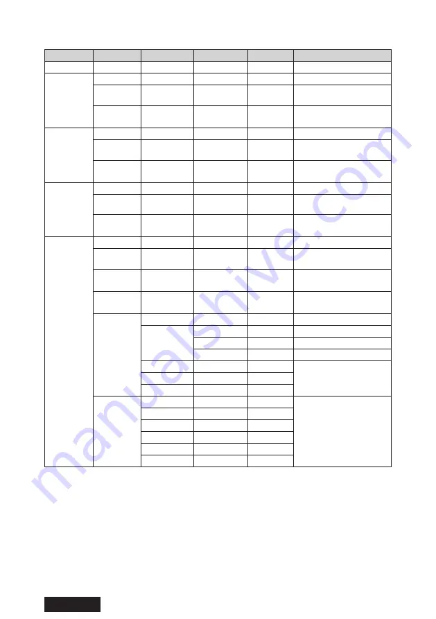
Function list of OSD adjustment

LEVEL 1

LEVEL 2

LEVEL 3

LEVEL 4

Default

DESCRIPTION

Exit

Config1 *

Exit
Backlight

Adjust the brightness 

of screen

Contrast

90

Adjust the contrast of 

images

Config2

Exit
Backlight

Adjust the brightness 

of screen

Contrast

90

Adjust the contrast of 

images

Config3

Exit
Backlight

Adjust the brightness 

of screen

Contrast

90

Adjust the contrast of 

images

User Mode

Exit
Backlight

50

Adjust the brightness 

of screen 

Contrast

90

Adjust the contrast of 

images

Black level

50

Adjust the brightness 

of black on images

Color

Exit

User

Red

100

Adjust red on images

Green

100

Adjust green on images

Blue

100

Adjust blue on images 

5800K

Select white balance

6500K

7500K *

Gamma

Exit

Select Gamma 

(luminance response) 

of images

Gamma 2.0

Gamma 2.2

Gamma 2.4

DICOM *

Native

Summary of Contents for CL-R813

Page 1: ...nt This instruction manual contains important information on how to use the product Please make sure to read the safety precautions first and keep this manual in a safe and easily accessible place for future reference B5A 4312 00 Model CL R813BN0UA CL R813BN0EA ...

Page 2: ... 2 All other products and company names are trademarks of their respective owners ENGLISH ...

Page 3: ...ion 27 Reference 32 Operating Principle 32 Attaching an arm stand 33 Anti Theft security slot 34 How to change the fuse 35 Cable management 36 Supported signals 37 Connector pin assignment 38 Technical specification 39 Hardware Software compatibility 41 Performance specifications 42 When a failure is suspected 43 Cleaning the monitor 44 After sales service 45 Disposal of Electrical and Electronic ...

Page 4: ...es or related to the time limit business decrease in profits any delay any information and other financial disadvantages arising from the use of software provided by us for this product even if we have been advised of the possibility of such damages Uninterruptible power supply Instantaneous voltage drop due to for instance lightning could cause a power failure We recommend that an uninterruptible...

Page 5: ...2 This device must accept any interference received including interference that may cause undesired operation Conformity This device complies with the requirements of the European Medical Device Regulation EU 2017 745 MDR Medical Device Classification Class I Manufacturer JVCKENWOOD Corporation 3 12 Moriya cho Kanagawa ku Yokohama shi Kanagawa 221 0022 JAPAN Authorized representative JVCKENWOOD De...

Page 6: ...I equipment Protection against harmful ingress of water Ordinary Equipment IPX0 No protection Not suitable for use in the presence of flammable anesthetics or oxygen Mode of operation Continuous operation Power Cord Important Information CAUTION Please use the power cord provided with this monitor in accordance with the table below If a power cord is not supplied with this equipment please contact...

Page 7: ...tional equipment connected to this product needs to comply with the requirements of IEC 60601 1 2 2014 EN 60601 1 2 2015 Environments of Intended Use The model CL R813 is intended to be used in Home healthcare environment such as residences and nursing homes Guidance and Manufacturer s Declaration Electromagnetic Compatibility Guidance and manufacturer s declaration electromagnetic emissions The m...

Page 8: ...th 1 kV line s to line s 2 kV line s to earth Mains power quality should be that of a typical commercial or hospital environment Voltage dips short interruptions and voltage variations on power supply input lines IEC 61000 4 11 0 UT 100 dip in UT 0 5 cycles and 1 cycle 70 UT 30 dip in UT 25 30 cycles 0 UT 100 dip in UT 250 300 cycles 0 UT 100 dip in UT 0 5 cycles and 1 cycle 70 UT 30 dip in UT 25 ...

Page 9: ...alculated from the equation applicable to the frequency of the transmitter Conducted RF IEC 61000 4 6 3 V 0 15 MHz to 80 MHz 6 V ISM bands and amateur radio between 150 kHz and 80 MHz 80 AM at 1 kHz 3 V 0 15 MHz to 80 MHz 6 V ISM bands and amateur radio between 150 kHz and 80 MHz 80 AM at 1 kHz Recommended separation distance d 1 2 Radiated RF IEC 61000 4 3 10 V m 80 MHz to 2 7 GHz 10 V m 80 MHz t...

Page 10: ... to 10 15 MHz 14 MHz to 14 2 MHz 18 07 MHz to 18 17 MHz 21 0 MHz to 21 4 MHz 24 89 MHz to 24 99 MHz 28 0 MHz to 29 7 MHz and 50 0 MHz to 54 0 MHz a Field strengths from fixed transmitters such as base stations for radio cellular cordless telephones and land mobile radios amateur radio AM and FM radio broadcast and TV broadcast cannot be predicted theoretically with accuracy To assess the electroma...

Page 11: ...Hz Bandwidtha MHz Servicea Modulationb Maximum power W Minimum separation distance m IEC EN 60601 test level V m Compliance level V m 385 380 390 TETRA400 Pulse modulationb 1 8 0 3 27 27 450 430 470 GMRS 460 FRS 460 FM 5 kHz deviation 1 kHz sine 2 0 3 28 28 710 704 787 LTE Band 13 17 Pulse modulationb 217 Hz 0 2 0 3 9 9 745 780 810 800 960 GSM 800 900 TETRA 800 iDEN 820 CDMA 850 LTE Band 5 Pulse m...

Page 12: ...3 8 3 8 7 3 100 12 12 23 For transmitters rated at a maximum output power not listed above the recommended separation distance d in meters m can be estimated using the equation applicable to the frequency of the transmitter where P is the maximum output power rating of the transmitter in watts W according to the transmitter manufacturer NOTE 1 At 80 MHz and 800 MHz the separation distance for the ...

Page 13: ... 13 ENGLISH Label Important Please read the label containing warnings and cautions carefully before use ...

Page 14: ...ed UK MDR 2002 Indicates compliance with Part 15 of the FCC rules Class B VCCI Notice Japan Only Indicates the compliance to the Class B product based on the standard of the Voluntary Control Council for Interference VCCI Indicates compliance with EMC standards of Oceania Indicates this apparatus must be recycled according to the European WEEE directive Symbol for MANUFACTURER Symbol for AUTHORIZE...

Page 15: ...r or moderate personal injury or property damage Meanings Calls your attention to warnings or cautions This sign may contain a picture of a specific situation E g risk of electric shock Indicates a banned action This sign may contain a picture of a specific situation E g no disassembly Indicates you must follow the instructions This sign may contain a picture of a specific situation E g Unplug fro...

Page 16: ...ything over the cables It could cause the monitor to fail or cause fire Do not handle the monitor with wet hands It could cause the monitor to fail or cause electric shock No modification of this equipment is allowed Do not modify this equipment without authorization of the manufacturer If this equipment is modified appropriate inspection and testing must be conducted to ensure continued safe use ...

Page 17: ...e damage and result in fire or electric shock Do not plug unplug with wet hands It could cause electric fire Dust the plug periodically and keep it dust free to avoid fire or electric shock Do not overload wall outlets It could cause fire or electric shock Do not put things around the monitor Keep enough space around for easy access to the plug Turn off and unplug the monitor and its peripheral de...

Page 18: ...isconnection This product can be reused only if it is reconditioned under our responsibility Please report to us and the authority of the member state if in any serious incident that has occurred in relation this product LCD Even if it is used properly the monitor may cause harmful interference to radio or television reception Try the following measures to correct it Increase the distance between ...

Page 19: ...or once a year The dust could cause fire Ask your dealer for maintenance Mounting orientation is landscape only Product Security This product is operated by the dedicated microcomputer system To delete or alter the program could lead to abnormal display When this product is controlled by a computer do not unplug the USB cable connected to this product Connection to IT Network Connecting to IT Netw...

Page 20: ... For the U S 2P For Europe DisplayPort cable 2 DP DP 3 0 m USB cable 3 0 m DVI cable DVI DVI 3 0 m Instruction manual 1 English Japanese Utility disk Utility disk This product is packed with Utility disk Functions such as calibration display of test patterns and so on can be done by installing this disk QA Medivisor Agent LE to your PC Please refer to the manual on the disk for its usage and the i...

Page 21: ...ort in daisy chain it gets much easier to organize wires Luminance Uniformity correction feature Uniformity correction function to provide uniformity of luminance Corrects luminance unevenness which arising from the LCD panel Luminance stabilizing system Provides stable luminance for a long period of time by our unique built in luminance stabilizing system circuit Interchangeable stand The tilt st...

Page 22: ...d hold the key to turn on off the monitor Wait at least 5 seconds between on off actions OSD control key 1 Shown OSD menu and makes function operation by using other three OSD control keys OSD control key 2 Shown OSD menu and makes function operation by using other three OSD control keys OSD control key 3 Shown OSD menu and makes function operation by using other three OSD control keys OSD control...

Page 23: ...ltiple monitors via this port Display port_DisplayPort IN 1 Digital video signal input port Connect a Display Port cable Display port_DisplayPort IN 2 Digital video signal input port Connect a Display Port cable DVI D_DVI D Connect the supplied DVI D cable UP USB upstream port When connecting a USB device to DOWN connect one end of the supplied USB cable to the monitor s UP and the other end to th...

Page 24: ...t the supplied DVI D cable to the DVI D port on this product and the DVI D port on the computer Note Use the supplied cables If you don t use them the monitor may become unstable and the screen may flicker 3 Connect the supplied USB cable to the UP stream port on this product and the DOWN stream port on the computer or other USB hub when the product is controlled configuration change or quality co...

Page 25: ...le monitors in daisy chain Please connect multiple monitors together using DisplayPort as below 1 2 DisplayPort cable DisplayPort cable To the DisplayPort output of the computer Not support DisplayPort_IN2 Connect to DisplayPort_IN1 ...

Page 26: ...tor turns 45 degrees sideways 5 degrees downward and 20 degrees upward Hold the monitor with both hands and adjust the angle slowly 20 degrees 45 degrees 5 degrees 45 degrees Be careful not to pinch your fingers when adjusting the panel angle Caution ...

Page 27: ...ey 1 Stand by key Item of key guide EXIT Backlight Source MENU Operation Turns off Operation Key Guide Shown the level bar for backlight adjustment Switched Menu to select input signal Shown Main menu OSD Activate stand by mode after pressing one second Main menu OSD appears by pressing MENU key OSD control key 1 the items on the key guide change you can move a cursor by using or key The color of ...

Page 28: ...onfig3 Exit Backlight Adjust the brightness of screen Contrast 90 Adjust the contrast of images User Mode Exit Backlight 50 Adjust the brightness of screen Contrast 90 Adjust the contrast of images Black level 50 Adjust the brightness of black on images Color Exit User Red 100 Adjust red on images Green 100 Adjust green on images Blue 100 Adjust blue on images 5800K Select white balance 6500K 7500...

Page 29: ...ng PbyP ON Layout 2 Layout 3 Layout 4 sub select Exit Auto Select Exit Select Auto Select on sub window On Off DP 1 Select input source of sub window DP 2 DVI Main Sub SW Switch Main window and Sub window Scaling Exit Full Full screen 1 1 Maintain resolution and display images Fit Maintain aspect ratio and display images Language Exit Select OSD language English Français Deutsch Italiano Español 日...

Page 30: ...nt by human sensor Sensitivity 2 4 6 8 10 12 14 16 Set up the sensitivity of a sensor DisplayPort Setting Exit DP1 1 Select the version of DisplayPort DP1 2 DP POWER Exit Set up the power of DisplayPort on power management On Off Information Model CL R813 Shown model name S N Lxxxxxxxxx Shown serial number Source xxx Shown the information of the selected signal Fh Fv xxx xkHz xx xHz FW ver xxxxxxR...

Page 31: ...uman presence sensor is on the power save mode is low Off Power save mode high Monitor won t turn on when turning on your computer from sleep mode Press the stand by key or the main switch How to set Power management HUMAN SENSOR and DP POWER Stand by key HUMAN SENSOR DP POWER LED Mode Normal ON OFF ON Green Power save 1 ON ON ON Orange Power save mode low Power save 2 ON ON Orange Power save mode...

Page 32: ... are not failures Note Turn off the system when connecting and disconnecting the signal cables It could damage the graphics card Operating Principle Image signals from acquisition devices or picture archiving communication system PC shall be transmitted to the monitor via DVI or DisplayPort terminals By transmitting image signals of the system to the input unit of the monitor the monitor can provi...

Page 33: ...nection becomes loose and the monitor could fall off Mounting plate thickness Screw size 3 5 4 5 mm ISO M4 12 1 5 3 5 mm ISO M4 10 Originally used Below 1 5 mm ISO M4 8 Note We are not liable for any damage or injury resulting from replacing stands Caution How to attach an arm stand 1 Place a soft cloth or cushioning material over a stable even surface 2 Put the monitor face down on the soft cloth...

Page 34: ...y slot This monitor has a built in Kensington Security Slot by ACCO Brands Corporation Please purchase the MicroSaver lock at PC supply stores separately Kensington and MicroSaver are registered trademarks of ACCO Brands Corporation ...

Page 35: ...use Note for AC INLET with fuse AC Inlet has a built in fuse When replacing the fuse be sure to use only a correctly rated approved type re fit the fuse cover How to replace the fuse Open the fuse compartment with the blade screwdriver and replace the fuse ...

Page 36: ... 36 ENGLISH Cable management Please use the cable hole when plugging in the computer and monitor so that cables will be organized Cable hole Cable ...

Page 37: ... be displayed normally when selecting other than the timing shown in the table below Resolution Vertical Frequency Hz DisplayPort DVI D 720 400 70 640 480 60 800 600 60 1024 768 60 1280 1024 60 1600 1200 60 1920 1080 60 1920 1200 60 1920 2160 60 30 Hz 2048 1536 60 3840 2160 60 30 Hz ...

Page 38: ... Clock Shield 11 TMDS Data 1 3 Shield 23 TMDS Clock 12 TMDS Data 3 24 TMDS Clock DisplayPort receptacle connector Pin Signal Pin Signal 1 ML_Lane 3 n 2 GND 3 ML_Lane 3 p 4 ML_Lane 2 n 5 GND 6 ML_Lane 2 p 7 ML_Lane 1 n 8 GND 9 ML_Lane 1 p 10 ML_Lane 0 n 11 GND 12 ML_Lane 0 p 13 CONFIG1 14 CONFIG2 15 AUX CH p 16 GND 17 AUX CH n 18 Hot Plug Detect 19 Return 20 DP_PWR USB Type B receptacle connector U...

Page 39: ... port 1 USB downstream ports 3 Environmental Conditions Operating Transport Storage Temperature 5 to 40 C 20 to 60 C 41 to 104 F 4 to 140 F Humidity no condensation 30 to 80 10 to 85 Air pressure 566 to 1060 hPa 266 to 1060 hPa Operating temperature range that ensures optimal performance of the monitor is 20 to 35 C 68 to 95 F Wet bulb temperature Max 38 C 100 4 F Ta 40 C 104 F The monitor install...

Page 40: ... 40 ENGLISH External dimensionsor single screen 196 5 61 6 240 487 5 582 5 435 217 742 Unit mm ...

Page 41: ... Part No Manufacturer Notes Graphics card LV N402 JVCKENWOOD Calibration kit CAL 016 JVCKENWOOD QA Medivisor Agent Ver 1 10 1 or Later and Calibrator T4 external sensor are included Utility Disk PSW22 295x JVCKENWOOD Attached to the product LCD Monitor CL R190 CL R211 CV F238 CL S200 MS S200 JVCKENWOOD Connect to the output port of CL R813 as a secondary monitor OS Windows10 Microsoft ...

Page 42: ... 2 Class II Artifacts By visible check of AAPM TG18 no ringing ghosting image sticking Temporal response Level Rise Fall msec Typ 0 100 7 0 6 3 5 95 8 2 6 4 10 90 9 0 6 8 40 60 10 7 10 9 Luminance maximum minimum achievable and recommended Achievable Lmax 500 cd m2 Lmin 0 5 cd m2 Recommended Lmax 280 cd m2 Lmin 0 5 cd m2 Conformance to DICOM GSDF Kδ deviation to DICOM GSDF 10 ...

Page 43: ...ignal frequency or display resolution may not be appropriate for the monitor Refer to the computer instruction manual and adjust the frequency and or resolution No Signal appears Check if signal cables are connected correctly P24 Check if your computer turns on The monitor resolution may not be appropriate for the monitor Refer to the computer instruction manual and adjust resolution LED indicator...

Page 44: ...e coating could come off Do not spray insecticides and other volatile solutions on the cabinet Do not keep rubber or vinyl in contact with the cabinet for a long time It could damage the cabinet and or the coating could come off Wipe the panel surface with a soft dry cloth lightly moistened with water or diluted neutral detergent Finish up by wiping with a dry soft cloth Commercially available cle...

Page 45: ... be available for a fee upon request Use the original box and packing material to pack the product for shipping Make sure that the LCD panel does not come in contact with the packing material when packed It could damage the panel We are not liable for such damage Please provide the following information when contacting your dealer Model name Serial number Date of purchase Detailed description of t...

Page 46: ...e disposed as household waste Old electrical and electronic equipment and batteries should be recycled at a facility capable of handling these items and their waste byproducts Contact your local authority for details in locating a recycle facility nearest to you Proper recycling and waste disposal will help conserve resources whilst preventing detrimental effects on our health and the environment ...

Page 47: ...ly may be reproduced or copied without authori zation The content of this manual is subject to change without notice Although this manual has been prepared carefully please let us know if you find any errors omissions or ambiguous explanations CL R813 Instruction Manual October 2022 Edition ...

Page 48: ... 48 ENGLISH Printed in Japan 2022 JVCKENWOOD Corporation 3 12 Moriya cho Kanagawa ku Yokohama shi Kanagawa 221 0022 JAPAN ...

Page 49: ... 1 日本語 32 型 81 3 cm カラー液晶モニター 取扱説明書 この取扱説明書をよくお読みいただき 正しくお使いください また ご使用前に必ず 安全上の注意 を読んで正しくお使いください 取扱説明書 はできる限り身近なところで大切に保管してください Model CL R813BN0JA ...

Page 50: ... 2 日本語 記載されている会社名および商品名は各社の登録商標または商標です ...

Page 51: ...て 13 付属品を確認してください 14 製品の特長 15 各部の名称と働き 16 接続のしかた 18 モニターの角度調整 20 操作方法 21 参考 26 市販のアームを取り付けるときは 27 盗難防止セキュリティロックスロット 28 ヒューズの交換 29 ケー ブルマネジメント 30 対応信号 31 入力信号 32 仕様 33 故障かな と思ったら 35 お手入れについて 36 製品を廃棄するときは 36 アフターサービス 37 保証書 裏表紙 3 日本語 ...

Page 52: ...本製品は 日本国内仕様です 本製品を日本国外に輸出する際は 事前に製品に関する営業窓口にご相談頂き 輸出者の責任 において 最終仕向地の関連法令を遵守し 必要な手続きを行ってください 海外の法令及び規制への適合について 当社では責任を負いかねます 責任制限 火災 地震 第三者による行為 その他の事故 使用者の故意または過失 誤用 その他異 常な条件下での使用により生じた損害に関して 当社は一切責任を負いません 本製品の使用または使用不能から生ずる付随的な損害 事業利益の損失 事業の中断 記憶 内容の変化 消失など に関して 当社は一切責任を負いません 分解や改造をした場合 当社は一切責任を負いません 取扱説明書で説明された以外の使い方によって生じた損害に対して 当社は一切責任を負いま せん 接続機器との組み合わせによる誤動作などから生じた損害に対して 当社は一切責任を負いま せん 本製品の...

Page 53: ...機に近接して使用されると 受信障害を引 き起こすことがあります 取扱説明書に従って正しい取り扱いをしてください VCCI B JIS C 61000 3 2 適合品 本製品は 高調波電流規格 JIS C 61000 3 2 に適合しております 瞬時電圧変動について 本製品は 落雷などによる電源の瞬時電圧低下に対し不具合を生じることがあります 電源の 瞬時電圧低下対策としては 交流無停電電源装置等を使用されることをお薦めします 注意 警告表示について 本製品の背面には 注意 警告表示があります お使いになる前に 内容をよく読んで安全にお使いください 5 日本語 ...

Page 54: ...電源コードが付属されていない場合は 購入元にお問い合わせください その他の国で使用する場合 コンセントの交流電圧と一致した その国の安全基準によっ て認証されている電源コードをご使用ください 北米では医用モニターにはホスピタル グレードの電源コードを使用しなければなりません 国 米国 カナダ 欧州 日本 プラグ形状 または 標準 UL CSA VDE Demko Nemko BSI 等 PSE 電圧 120 230 100 注記 この製品は 購入された国でのみ修理サービスを受けることができます 6 日本語 ...

Page 55: ...の修正版 UK MDR 2002 の要件に適合し ていることを示しています 米連邦通信委員会 FCC の規格に適合していること を示しています この装置は VCCI 協会のクラスB情報技術装置です オセアニア諸国の EMC 規格に適合しているマークです 欧州の WEEE 指令マークです MANUFACTURER の記号です AUTHORIZED REPRESENTATIVE IN THE EUROPEAN COMMUNITY の記号です 取扱説明書を参照してください これが医療機器であることを示します UK Responsible Person の記号です 交流電源マークです 電源のスタンバイ 準備中 マークです メイン電源スイッチ ON メイン電源スイッチ OFF 7 日本語 ...

Page 56: ...可能性が想定される内容 および物的損害のみの発生が 想定される内容を示しています 絵記号の意味 で示した記号は警告 注意を促す事項があることを告げるものです 記号の中には 具体的な警告内容が描かれています 例 感電注意 を表す絵記号 で示した記号は してはいけない行為 禁止行為 です 記号の中には 具体的な禁止内容が描かれています 例 分解禁止 を表す絵記号 で示した記号は 必ずしたがっていただく内容であることを告げるも のです 記号の中には 具体的な指示内容が描かれています 例 電源プラグをコンセントから抜いてください を表す絵記号 本文中の記号について 使用前に必ず読んでいただきたい内容を記述しています お使いになるときに注意していただきたいことや してはいけないことを記 述しています 操作に関することを記述しています 必要に応じてお読みください 本書内の参照ページを記述しています 8...

Page 57: ...す 禁止 本体の上にものを置いたり かぶせないでください そのまま使用を続けると故障や火災の原因になります 禁止 ケーブルの上にものを置いたり かぶせないでください そのまま使用を続けると故障や火災の原因になります ぬれ手禁止 濡れた手で本製品を取り扱わないでください 感電や本製品の故障の原因になります 電源プラグを 抜く 煙が出たり変な臭いや音がしたら すぐに本製品のメイン電源スイッチを切り 電源プラグをコンセントから抜いてください そのまま使用を続けると火災や感電の原因となります お買い求めの販売店にご相談ください 電源プラグを 抜く 本製品を落としたり 強い衝撃を与えたりした場合は すぐに本製品のメイン電 源スイッチを切り 電源プラグをコンセントから抜いてください 本製品は精密機器です そのまま使用を続けるとショートして火災や感電の原因 となります お買い求めの販売店にご相談ください...

Page 58: ...V 専用です 指定以外の電圧で使用しないでください 指定以外の電圧で使用した場合 発煙 発火など故障の原因となります 厳守 電源コードのアース接続 接地 をしてください 故障や漏電のときに感電の原因となります 電源コードが 2P プラグの場合 アース接続は必ず電源プラグをコンセントにつ なぐ前に行ってください また アース接続をはずす場合は 必ず電源プラグを コンセントから抜いてから行ってください 厳守 電源プラグの接続に関しては以下に注意してください 電源プラグを抜くときはプラグ部分を持つ コードを引っ張るとコードが傷ついて火災 感電の原因になります ぬれた手で電源プラグを抜き差ししない 感電の原因になります 電源プラグはほこりなどが付着していないように定期的に清掃する 火災 感電の原因になります タコ足配線しない 火災 感電の原因になります 電源プラグの周辺にものを置かない 異常時に電...

Page 59: ...の点にご注意ください 本機とラジオ テレビを十分離してご使用ください 本機とラジオ テレビを別のコンセントに接続してください 禁止 液晶パネル面を強く押したり ひっかいたり 上にものを置いたりしないでくだ さい 干渉縞が発生するなど表示異常を起こしたり パネルに傷が付いたりして液晶 パネル故障の原因になります 禁止 次のような場所に設置しないでください 強い磁界の発生する場所 振動の発生する場所 腐食性のガスが発生する場所 静電気の発生する場所 故障の原因となります 禁止 本製品は 結露したまま使わないでください 本製品を寒い部屋から暖かい部屋に移動すると 表面や内部が結露する場合が あります 必ず結露がなくなってからお使いください そのまま使うと故障の原 因になります 禁止 モニターをあお向けで使用したり 換気できないところに組み込んでの使用は しないでください 内部温度上昇により キャ...

Page 60: ...寒い所でご使用になると 画像が尾を引いて見えたり 画面が暗く見えたりす ることがありますが 故障ではありません 温度が上がると元に戻ります 本製品は 表示する条件により微少な斑点およびムラが目立つこともあります が 故障ではありません 液晶パネルは非常に高精度な技術を駆使し 有効画素数 99 999301 以上 として作られていますが 一部に表示不良画素 欠け 常時点灯など が存在 することがあります 厳守 暗い部屋で使用するときは 液晶モニターの輝度を上げすぎないでください 100 lx 以下の暗い環境下では 液晶モニター輝度を最大にしたり またはそれ に近い輝度で長時間使用しないでください 目を痛めて視力が低下する原因となります 工場出荷設定輝度 280 cd m2 での使用をお薦めします また 輝度調整を最小にしていますと見えにくい場合があります 厳守 年に一度はモニター内部の掃除を...

Page 61: ...理 する場合 本製品に 接続している USB ケーブルを抜かないでください 注意 IT ネットワークへの接続に関して IT ネットワークへの接続には想定しないリスクが生じる可能性があります IT ネットワーク接続の変更には新たなリスクが生じる可能性があります 変更には 構成の変更 機器の追加 機器の取り外し 機器の更新を含め ます これらのリスクを特定し リスクマネジメントをしてください 厳守 本製品をセキュアな状態でご使用いただくために 本製品と接続して使用す るワークステーションにおいて 下記のセキュリティ対策を適用して使用し てください アンチウィルス対策ソフトウェアのインストール ファイアーウォールの有効化とポート制御 ...

Page 62: ...ー本体 電源コード 3 0 m DisplayPort ケー ブル 2 DP DP 3 0 m USB ケー ブル 3 0 m DVI ケー ブル DVI DVI 3 0 m 取扱説明書 1 英語 日本語 ユーティリティディスク ユーティリティディスクについて 本製品には ユーティリティディスク CD が付属しています このディスクには QA Medivisor Agent LE が収録されており コンピュータにインストールすることで キャリブレーションや 各種テストパター ン表示等の機能拡張が行えます インストール方法 使用方法については ディスク内の取扱説明書を参照してください 包装ケースは 輸送などのために保存しておいてください 14 日本語 ...

Page 63: ...ジーチェーン接続 10bit 入力に対応した DisplayPort を搭載しました 10bit 入力時には約 10 億 7374 万色の表示を実現します DisplayPort のデイジーチェー ン 数珠繋ぎ接続 対応により 複数モニター使用時の配線が シンプルになります 輝度の均一性を改善する機能搭載 輝度均一性を実現するユニフォミティ補正機能を搭載しました 画面全体の輝度ムラの少ない 表示を実現 輝度 明るさ 安定性 当社独自の自動輝度安定化回路の搭載により 長期間にわたり安定した輝度を実現しています アーム備え付け機能 スタンド部分は取りはずせますので アーム利用など設置環境に応じた使い方ができます 100 mm ピッチの取付器具に対応 15 日本語 ...

Page 64: ... ノーマル動作状態 3 オレンジ点灯 オン パワーマネージメント状態 スタンバイキー_ メイン電源スイッチがオンのとき 本製品の電源オン オフが行えます Note 電源のオン オフはキーをタッチし続けて行います また 電源オン オフは 5 秒以 上間隔を空けて行ってください OSD 操作キー 1 OSD メニュー表示や機能操作を他の 3 つの OSD 操作キーと合わせて行い ます OSD 操作キー 2 OSD メニュー表示や機能操作を他の 3 つの OSD 操作キーと合わせて行い ます OSD 操作キー 3 OSD メニュー表示や機能操作を他の 3 つの OSD 操作キーと合わせて行い ます OSD 操作キー4 OSD メニュー表示や機能操作を他の 3 つの OSD 操作キーと合わせて行い ます 各部の名称と働き 16 日本語 ...

Page 65: ...DisplayPort ケー ブルを接続します ディスプレイポート _DisplayPort IN 1 付属の DisplayPort ケー ブルを接続します ディスプレイポート _DisplayPort IN 2 付属の DisplayPort ケー ブルを接続します DVI D_DVI D 付属の DVI D ケー ブルを接続します USB UP ストリームポート _UP USB DOWN ストリームポートに USB 機器を接続する場 合に 付属の USB ケー ブルを本機の UP ストリームポートとコンピュータの USB ポートに接続 します USB DOWN ストリームポート _DOWN USB DOWN ストリームポートを 2 ポート装備して います 消費電流 1 ポート 500 mA 最大 までの USB 機器が接続できます ケーブル通し穴 USB DOWN ストリームポート ...

Page 66: ...場合 画面がち らつくなど表示が不安定になることがあります 3 コンピュータから本製品に対して操作 設定変更 精度管理 を行う場合には 付属の USB ケー ブルを 本製品の UP ストリームポートとコンピュータ または他の USB ハブ の DOWN ストリームポートに接続します 4 付属の電源コードを本製品の AC インレットとコンセントに接続します 5 本製品の電源をオンにして コンピュータの電源をオンにします 医療用途でお使いの場合 本製品は IEC 60601 1 認定機器に接続されることを意図 しています 本製品が IEC 60601 1 認定機器へ接続されていない場合は IEC 60601 1 IEC 60601 1 1 によるシステム評価が必要となります 付属の電源コード以外は使用しないでください 注意 2 3 4 アース付き 3P 電源コンセントへ コンピュータの DOW...

Page 67: ...るときは DisplayPort コネクタを下図のようにデイジーチェー ン接続します デイジーチェー ン接続が可能なモニターおよび推奨グラフィックスカードについては 当社の Web サイトをご確認ください 1 2 DisplayPort ケー ブル DisplayPort ケー ブル コンピュータの DisplayPort 出力へ DisplayPort_IN2 は 対応していません DisplayPort_IN1 に接続 19 日本語 ...

Page 68: ...モニターの角度調整 画面の角度は 左右にそれぞれ 45 度 下向きに 5 度 上向きに 20 度の調整ができます 調整は下の図のように液晶モニターを両手で持ち ゆっくり動かしてください 5 度 45 度 20 度 45 度 モニターの角度調整をするときはご注意ください 指をはさむおそれがあります 注意 20 日本語 ...

Page 69: ...作キー 2 OSD 操作キー 1 スタンバイ キー 表示 キーガイド EXIT Backlight Source MENU 動作 キーガイドを OFF します バックライト調 整バー表示に切 り替わります 入力信号選択メ ニューに切り替 わります メインメニュー OSD を表示しま す 約 1 秒間タッチ するとスタンバ イになります MENU キーをタッチするとOSDメニューの Main Menu ページが表示されます キーガイド の表示が変化し または キーでカーソルを移動できます カーソルで選択した項目も文字は 白色に表示します カーソルで選択し ENTER キーをタッチして決定します メインメニューOSD 設定している項目をラジオボタンで 表示しています Config1が設定さ れています Exit カーソルは Exit にあります 表示している信号入力 表示している信号情報 21 ...

Page 70: ...像のコントラストを調整し ます Config3 Exit Backlight 画面の明るさを調整します Contrast 90 画像のコントラストを調整し ます User Mode Exit Backlight 50 画面の明るさを調整します Contrast 90 画像のコントラストを調整し ます Black level 50 画像の黒の明るさを調整し ます Color Exit User Red 100 画像の赤色を調整します Green 100 画像の緑色を調整します Blue 100 画像の青色を調整します 5800K 色合いを選択します 6500K 7500K Gamma Exit 画像の Gamma 階調 特性 を選択します Gamma 2 0 Gamma 2 2 Gamma 2 4 DICOM Native 22 日本語 ...

Page 71: ... アウトを選択 PbyP ON を時に有効です Layout 2 Layout 3 Layout 4 sub select Exit Auto Select Exit Sub 画面の自動選択を オン オフします On Off DP 1 Sub 画面の信号ソースを 選択します DP 2 DVI Main Sub SW Main 画面 と Sub 画面 を切り替えます Scaling Exit Full 画像を画面全体の表示 します 1 1 画像の解像度を保持して 表示します Fit 画像のアスペクト比を保持 して画面全体に表示します Language Exit OSD に表示する言語を 選択します English Français Deutsch Italiano Español 日本語 Source Exit Auto Select Exit メイン画面の自動選択を オン オフします On...

Page 72: ...in 人感センサーによるパワー マネージメントの設定を行 います Sensitivity 2 4 6 8 10 12 14 16 人感センサーの感度を 設定します DisplayPort Setting Exit DP1 1 DisplayPort のバージョン を選択します DP1 2 DP POWER Exit パワーマネージメント時 の DisplayPort の電源を 設定します On Off Information Model CL R813 モデル名です S N Lxxxxxxxxx 製品シリアル番号です Source xxx 表示している信号の情報 です Fh Fv xxx xkHz xx xHz FW ver xxxxxxRxVxx 製品のファームウエア バージョンです Ambient sensor xxx lx 周囲の明るさを表示し ます Front sensor xxx...

Page 73: ...ンピュータがスリー プモードから復帰してもモニターはオンになりません モニターのスタンバイキーまたはメインスイッチを一旦OFFにしてからONにしてくださ い パワーマネージメントと HUMAN SENSOR DP POWER の設定 スタンバイ キー HUMAN SENSOR DP POWER LED 状態 通常動作 ON OFF ON グリーン パワーセー ブ 1 ON ON ON オレンジ 浅いパワーセーブ パワーセー ブ 2 ON ON オレンジ 通常パワーセーブ パワーセー ブ 3 ON OFF オレンジ 深いパワーセーブ スタンバイ OFF OFF スタンバイモード 主電源 OFF OFF OFF コンフィグレーション設定 CL R813は工場出荷状態で下記3種類のコンフィグレーションを設定しています コンフィグレーション 輝度 cd m2 色温度 ガンマ 最大 最小 Confi...

Page 74: ...ード移行の時間設定については ご使用のコンピュータの 取扱説明書等をご覧ください デジタル入力でのご利用 本製品の入力信号は デジタル入力となっています 本信号の場合 接続されているシステムの 起動および終了の過程 解像度切り替え時にノイズ等が表示されることがあります これは システムのグラフィックスカードが解像度切り替えで発生するノイズです 本製品の故障ではあ りませんので ご了承ください また 使用中に信号ケー ブルを抜き差しされますと システムのグラフィックスカード故障の原 因となります ケー ブルの抜き差しは必ずシステムの電源を OFF にしてから行ってください 26 日本語 ...

Page 75: ...品を破損したり ネジの寸法が短すぎる 場合は 落下するおそれがあります 取り付け部分の板金厚 指定ネジ寸法 3 5 4 5 mm ISO M4 12 1 5 3 5 mm ISO M4 10 添付品 1 5 mm 以下 ISO M4 8 なお スタンドの取りはずしやアーム取り付けはお客様の責任において行うものとし 万一事故が発生した場合 当社はその責を負いかねますのでご承知ください 警告 アームの取り付け方 1 液晶パネル面に傷がつかないよう 安定した平らな面にクッション材または柔らかい布を敷き ます 2 その上に液晶パネル面を下にして本製品を置きます 3 スタンドを取りはずします プラスドライバーで下図矢印4 カ所のネジをはずします クッション材 または柔らかい布 4 液晶モニターをアームに取り付けます 逆の手順で行います すでに固定されたアームに液晶モニターを取り付けるような場合は は...

Page 76: ...盗難防止セキュリティロックスロット 本製品の背面カバーには ACCO Brands 社のKensington MicroSaver セキュリティロックシステ ムに対応したセキュリティロックスロットを搭載しています マイクロセイバーロックは 別途コンピ ュータ用品販売店などでお求めください Kensington MicroSaver は米国 ACCO Brands 社の登録商標です 28 日本語 ...

Page 77: ...ヒューズの交換 ヒューズ付きAC インレットの注意 AC インレットにはヒューズが内蔵されています ヒューズを交換するときは 正当な定格のタイプのみを使用してヒューズカバーを取り付け直して ください ヒューズの交換方法 マイナスドライバでヒューズカバーを開き ヒューズを交換します ヒューズ定格 T2 5AL 250 V 29 日本語 ...

Page 78: ...ケー ブルマネジメント ケー ブルの接続時には スタンドのケー ブルホールを使用してまとめて配線してください ケーブルホール ケーブル 30 日本語 ...

Page 79: ...グ 下表タイミング以外の場合 正常に映らない事があります 解像度 垂直周波数 Hz DisplayPort DVI D 720 400 70 640 480 60 800 600 60 1024 768 60 1280 1024 60 1600 1200 60 1920 1080 60 1920 1200 60 1920 2160 60 30 Hz 2048 1536 60 3840 2160 60 30 Hz 31 日本語 ...

Page 80: ... 20 TMDS Data 5 9 TMDS Data1 21 TMDS Data 5 10 TMDS Data1 22 TMDS Clock Shield 11 TMDS Data 1 3 Shield 23 TMDS Clock 12 TMDS Data 3 24 TMDS Clock 1 4 USB コネクタ タイプ A リセプタクル DOWN USB No 信 号 1 VCC 2 DATA 3 DATA 4 GND No 信 号 No 信 号 1 ML_Lane 3 n 2 GND 3 ML_Lane 3 p 4 ML_Lane 2 n 5 GND 6 ML_Lane 2 p 7 ML_Lane 1 n 8 GND 9 ML_Lane 1 p 10 ML_Lane 0 n 11 GND 12 ML_Lane 0 p 13 CONFIG1 14 CONFIG2 15 AUX CH p...

Page 81: ...コネクタ 1 出力端子 DisplayPort OUT コネクタ 1 USB ハブ機能 USB 規格 Rev 2 0 準拠 セルフパワードハブ USB UP ストリームポート 1 USB DOWN ストリームポート 3 環境条件 動作 輸送および保存 温度 5 40 1 20 60 湿度 非結露 30 80 10 85 2 気圧 566 1060 hPa 266 1060 hPa 1 性能保証温度は 20 35 です 2 湿球温度は Max 38 Ta 40 電源 100 240 V 2 2 1 1 A 50 60 Hz 外形寸法 W H D 本体 742 0 487 5 582 5 196 5 mm 梱包時 862 0 317 0 618 0 mm mm 質量 本体 約 10 0 kg スタンドを除く 約 7 0 kg 梱包時 約 14 8 kg キャリブレーションキット オプション キ...

Page 82: ...外形図 単位 mm 196 5 61 6 240 487 5 582 5 435 217 742 34 日本語 ...

Page 83: ...が Off になっている可能性があります スタンバイキーでモニターを ON するか メイン電源スイッ チを入れなおしてください 入力信号の周波数もしくは表示解像度が本製品の仕様に適 合していない可能性があります コンピュータの取扱説明書 にしたがって 周波数または表示解像度を調整してください No Signal という OSD が表 示される 信号ケー ブルの接続を確認してください P18 コンピュータの電源が入っているか確認してください 入力信号の表示解像度が本製品の仕様に適合していない可 能性があります コンピュータの取扱説明書にしたがって 表示解像度を調整してください LED インジゲータが グリー ン点 滅を繰り返す メイン電源スイッチを OFF してから もう一度 ON にしてく ださい 症状が改善されない場合は 弊社サポートデスク へお問い合わせください コンピュータの画像が正し...

Page 84: ...ネットのほこりは柔らかい布でふき取ってください 中性洗剤 エタノール イソプロピ ルアルコールで軽く湿らせて 油汚れを拭き取ります 使い捨ての布を使用する場合は 指示 に従ってください キャビネットはプラスチック製です シンナー ベンジンは塗布しないでください プラスチッ クが損傷したり コーティングがはがれたりする可能性があります キャビネットに殺虫剤や揮発性のものをかけたりしないでください また ゴムやビニール製品 などを長時間接触させたままにしないでください 変質したり塗料がはげるなどの原因になり ます 表示面の汚れは クリーニングクロスに水または水で薄めた中性洗剤を少量しみ込ませてや さしく拭き取り さらにクリーニングクロスの乾いた部分でもう一度拭いて仕上げてください 市販のクリーナーや弱アルカリ性洗剤を使用すると 表示面にダメージを与えることがありま す 表示面は慎重に取り扱って...

Page 85: ...あるときは 使用をやめて電源コードをコンセントから抜き JVC ケンウッド長岡フィー ルドサービスセンターにお問い合わせください ご自分での修理はしないでください 大変危 険です 保証期間中の修理は故障内容や使用状況により無料修理いたします 保証期間後の修理は JVC ケンウッド長岡フィールドサービスセンターにご相談ください 修理によって機能が維持できる場合は ご要望により有料修理いたします 修理依頼での輸送は 製品の梱包箱および梱包材をご使用ください 輸送時は 表示面に は梱包材が当たらない状態で送ってください 当たったまま輸送すると 液晶パネルの故障となることがあり その場合は保証いたしかねます 修理を依頼される場合にお知らせしていただきたい内容 お名前 ご住所 ご連絡先 電話番号 FAX 番号または E mail アドレス 製品のモデル名 製造番号 本機背面のラベルに記載 購入年月日...

Page 86: ...談窓口にご連絡くだ さい お問い合わせは アフターサービスのお問い合わせは 下記サービスセンターにご相談ください 修理に対するお問い合わせ 940 0006 新潟県長岡市東高見 1 2 1 株式会社 JVC ケンウッド長岡 フィールドサービスセンター 0120 24 2061 FAX 0258 24 6700 受付時間 月曜日 金曜日 9 00 12 00 13 00 17 00 土 日 祝祭日および当社休日は除く サポートに対するお問い合わせ 940 0006 新潟県長岡市東高見 1 2 1 株式会社 JVC ケンウッド長岡 サポートデスク 0120 24 2061 FAX 0258 24 6700 受付時間 月曜日 金曜日 9 00 12 00 13 00 17 00 土 日 祝祭日および当社休日は除く 製品に関する営業窓口 年間保守契約に対するご相談 221 0022 神奈川県横浜市...

Page 87: ...CL R813 取扱説明書 2022 年 10 月版 本書の内容の一部又は全部を無断転記することは禁止されています 本書の内容について将来予告なしに変更することがあります 本書は内容について万全を期して作成いたしましたが 万一ご不明な点や誤り 記載もれなど お気づきのことがありましたら販売店にご連絡ください 取扱説明書に関するご注意 39 日本語 ...

Page 88: ...は有償修理となります 1 保証書のご提示がない場合 2 保証書に必要事項 販売店および印 お買い上げ日 の記入のない場合および内容が書き 換えられた場合 3 液晶パネル及びバックライトの経時による劣化の場合 液晶パネル及びバックライトは消 耗品です 4 ご使用上の誤り 不当な修理や改造 誤接続による故障 損傷の場合 5 お客様による輸送 移動時の落下 衝撃等の取り扱い上生じた故障 損傷の場合 6 火災 地震 風水害 落雷およびその他の天災地変 公害 塩害 ガス害 異常電圧 指定外の電源使用等による故障 損傷の場合 7 車両 船舶などのような強い振動 衝撃が加わる場所に搭載されて生じた故障 損傷の場合 2 保証書にかかる当社の責任は 故障した本製品の修理を行うことに限られるものとします 3 本保証書は日本国内においてのみ有効です 4 本保証書は再発行いたしませんので大切に保管してください 5...

Reviews: