


(No.MB262)1-17
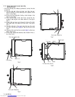
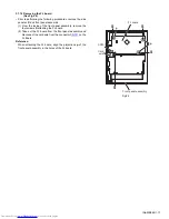
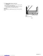
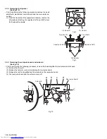
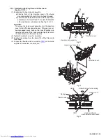
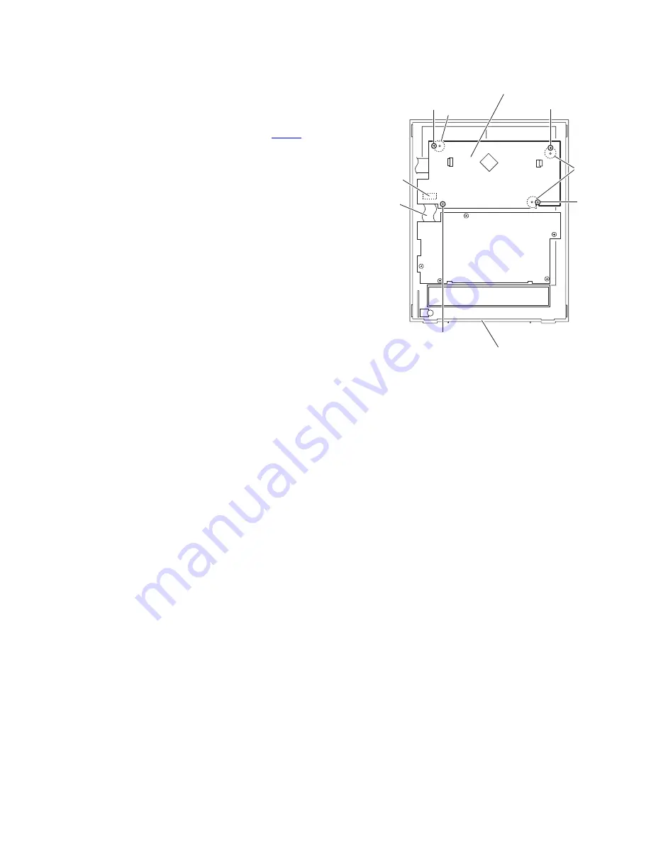
3.1.14 Removing the FL board
(See Fig.24)
• Prior to performing the following procedures, remove the side
panels L/R and front panel assembly.
(1) From the inside of the front panel assembly, remove the
four screws
S
attaching the FL board.
(2) Take out the FL board from the front panel assembly and
disconnect the card wire from the connector
CN751
on the
FL board.
Reference:
When attaching the FL board, align the projections
p
of the
front panel assembly in the holes of the FL board.
Fig.24
CN751
Card
wire
FL board
p
S
S
S
S
p
Front panel assembly


