


1-24 (No.MB262)
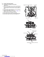
3.2.5 Attaching the CD pickup
(See Figs.7 to 10)
• See "3.2.4 Removing the CD pickup".
(1) Remove solders from the short land sections
k
after con-
necting the card wire to the connector on the CD pickup.
(See Fig.9)
(2) Attach the shaft. (See Fig.8)
(3) Align the CD pickup to the section
j
of the traverse mecha-
nism assembly first, and set the screw shaft of the CD pick-
up in the sections
i
of the traverse mechanism assembly.
(See Fig.8.)
(4) Attach the rack arm and feed middle gear. (See Fig.8)
(5) Attach the shaft holder. (See Fig.7)
(6) Turn the SS gear in the direction of the arrow 1 to move the
CD pickup in the direction of the arrow 2. (See Fig.10)
Fig.10
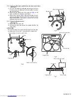
3.2.6 Removing the feed motor
(See Figs.5, 7 and 11)
• Remove the traverse mechanism assembly.
(1) From the top side of the traverse mechanism assembly, re-
move the wire (yellow) from the solder sections
d
on the
CD servo board. (See Fig.5)
(2) Remove the wire (white) from the solder sections
e
on the
CD servo board. (See Fig.5)
(3) Remove the screw
D
attaching the shaft holder and take
out the shaft holder. (See Fig.7)
(4) Remove the feed middle gear and remove the screw
E
at-
taching the feed motor. (See Fig.11)
(5) Take out the feed motor from the traverse mechanism as-
sembly.
Reference:
When attaching the feed motor, pass the wires through the
section
m
on the traverse mechanism assembly. (See Fig.11)
Fig.11
Traverse mechanism assembly
SS gear
Pickup
1
2
Traverse mechanism assembly
Feed middle gear
Feed motor
Section
m
Wires
E


