1-12 (No.MB262)
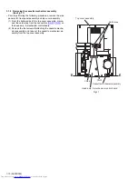
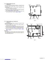
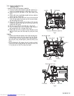
3.1.6 Removing the rear panel
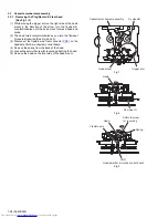
(See Fig.14)
• Prior to performing the following procedures, remove the side
panels L/R.
(1) From the back side of the main body, remove the eight
screws
G
attaching the rear panel.
(2) Release the engagement sections
e
and remove the rear
panel.
(3) Disconnect the wire from the connector
CN711
on the main
board.
Reference:
After connecting the wire to the connector
CN711
, fix the wire
with the wire holder.
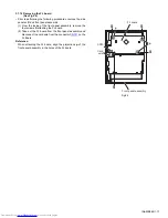
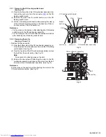
3.1.7 Removing the fan
(See Figs.14 and 15)
• Prior to performing the following procedures, remove the side
panels L/R and rear panel.
(1) From the outside of the rear panel, remove the two screws
H
attaching the fan bracket to the rear panel. (See Fig.14.)
(2) From the inside of the rear panel, move the fan bracket in
the direction of the arrow to release the engagement sec-
tions (
f
,
g
). (See Fig.15.)
(3) Remove the fan bracket from the rear panel and remove
the fan. (See Fig.15.)
Fig.14
Fig.15
Rear panel
H
G
G
e
e
CN711
Wire
holder
Wire
Main board
G
f
Fan bracket
Fan
Rear panel
g


