1-55
CA-MXS6MDR
SP-MXS6MD
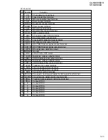
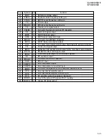
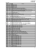
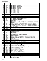
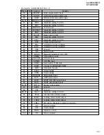
2. Pin function (2/2)
33
34
35
36
37
38
39
40
41
42
43
44
45
46
47
48
49
50
51
52
53
54
55
56
57
58
59
60
61
62
63
64
I
I
I
I
O
I
I
O
I
I
O
O
O
O
O
O
I
I
I
I
O
I
I
I
I
I
I
I
I
I
I
I
Tray 1 close signal input
Reference power supply voltage
Reference power supply voltage
CD reset signal input
Non connect
Reference power supply voltage
No use ( for Flash micon)
X'tal osc output
X'tal osc input
Ground
FLAG for C1 error
Sub Q block clock signal output
Cam motor rotation clockwise
Cam motor rotation counter clockwise
Actuator motor rotation counter clockwise
Actuator motor rotation clockwise
Gain select 2/4 speed
Equalizer select 2/4 speed
Cam position 3
Cam position 4
Reset signal output
Status signal input
Digital mute signal input
Power on signal input
Command load signal input
Command data input
Command clock input
Communication select signal input
Running data input from running jig
Running load 2 signal input from running jig
Running load 1 signal input from running jig
Running clock signal input from running jig
TRY1CLOSE
AVREF
AVDD
/RESET
XT2
XT1
IC
X2
X1
VSS1
FLAG
BLKCK
CAM_CW
CAM_CCW
ACT_CCW
ACT_CW
GCTRL
EQSW
ICAMP3
ICAMP4
/RESET
STAT
/DMUTE
/P.ON
MLD
MDATA
MCLK
SELECT
RUNDATA
RUNLOAD2
RUNLOAD1
RUNCLOCK
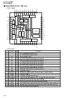
Pin
No.
Symbol
I/O
Function

