background image

No. 51944

AV28CH1EUS

AV28CH1EUB

8

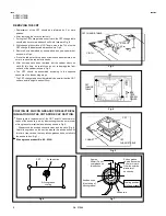
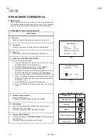
REMOVING THE CRT

 Replacement of the CRT should be performed by 2 or more

pers ons.

  After removing the c over, chassis etc.,

1.  Putting the CRT c hange table on soft cloth, the CRT change table

should also be c overed with s uch soft cloth (shown in Fig.3).

2.  While keeping the s urfac e of CRT down, mount the TV s et on the

CRT  change table balanced will  as shown in Fig.4.

3.  Remove 4 sc rews marked by arrows with a box type screw driver

as s hown in Fig.4.

  Sinc e the cabinet will drop when screws have been removed, be

sure to support the cabinet with hands.

4.  After 4 screws have been removed, put the cabinet slowly on

cloth (At this time, be carefully so as not to damage the front
surfac e of the c abinet) shown in Fig.5.

  The CRT should be ass embled according to the opposite

sequence of its dismounting steps.

  The CRT change table should preferably be smaller that the CRT

surfac e, and its height be about 35c m.

COATING OF SILICON GREASE FOR ELECTRICAL
INSULATION ON THE CRT ANODE CAP SECTION.

  Subsequent to replac ement of the CRT and HV transformer or

repair of the anode cap, etc. by dis mounting them, be sure to coat
silicon grease for electrical insulation as  shown in Fig.6.


Wipe around the anode button with clean and dry cloth. (Fig.6)


Coat silic on greas e on the section around the anode button. At
this time, take c are so that any silicon greas es dose not stic k to
the anode button. (Fig.7)

Silicon grease product No. KS  -  650N

CRT  CHANGE TABLE

CLOTH

APPROX.
35cm

CRT

CRT
CHANGE
TABLE

BOX
TYPE
SCREW
DRIVER

Fig. 3

Fig. 6

Fig. 7

Approx.
20mm (Do not
coat grease  on
this s ection

Silic on greas e
should be coated
by 5mm or more
from the outs ide
diameter of
anode c ap.

Anode button
(No sticking of
silicon grease)

Coating position
of silicon grease

Anode cap

Anode button

CRT

Silic on greas e

coating

Fig. 5

CRT

CABINET

CRT
CHANGE TABLE

Fig. 4

Summary of Contents for AV28CH1EUB

Page 1: ...APAN LTD Mar 2002 AV28CH1EUS AV28CH1EUB CONTENTS SPECIFICATIONS 2 SAFETY PRECAUTIONS 4 FEATURES 5 MAIN DIFFERENCE LIST 5 SPECIFIC SERVICE INSTRUCTIONS 6 SERVICE ADJUSTMENTS 12 PARTS LIST 31 STANDARD CIRCUIT DIAGRAM 2 1 SERVICE MANUAL COLOUR TELEVISION BASIC CHASSIS MF ...

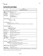
Page 2: ...12W Avg standby 2 8W Aerial Input Term 75Ωunbalanced Coaxial Picture Tube Visible size 66cm Measured diagonally High Voltage 30 0kV at zero beam current Speaker 10cm 3cm oval type 2 Audio Output 5W 5W EXT 1 EXT 2 EXT 3 Input Output 21 pin Euro connector SCART socket S Video Y 1Vp p POSITIVE Negative sync Provided when terminated with 75Ω C 0 3Vp p Burst signal when terminated with 75Ω EXT 4 Input ...
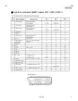
Page 3: ... impedance TV OUT LINE OUT NC 4 AUDIO GND 5 GND B 6 AUDIO L input 500mVrms Nominal High impedance 7 B input 700mVB W 75Ω NC 8 FUNCTION SW SLOW SW Low 0 3V High 8 12V High impedance 9 GND G 10 SCL3 NC NC 11 G input 700mVB W 75Ω NC 12 SDA3 NC NC 13 GND R 14 GND YS NC NC 15 R C input R 700mVB W 75Ω C 300mVP P 75Ω only R only C 16 Ys input Low 0 0 4 High 1 3V 75Ω NC NC 17 GND VIDEO output 18 GND VIDEO...

Page 4: ...nts or alternatives approved by the manufacturer of the complete product 7 Do not check high voltage by drawing an arc Use a high voltage meter or a high voltage probe with a VTVM Discharge the picture tube before attempting meter connection by connecting a clip lead to the ground frame and connecting the other end of the lead through a 10kΩ 2W resistor to the anode button 8 When service is requir...

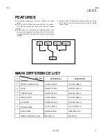
Page 5: ...in their original language Users can make VCR dubbing of picture and sound by controlling the AV selector to select an optional source at the EXT 2 output shown in figure MAIN DIFFERENCE LIST Model Name Part Name AV28CH1EUS AV28CH1EUB FRONT CABINET ASSY LC10001 008C U LC10001 009B U DOOR LC20001 010A U LC20001 012A U POWER KNOB LC30104 010A U LC30104 012A U REAR COVER LC1003 009B U LC10003 010B U ...

Page 6: ...REMOVING THE SPEAKER After removing the rear cover 1 Remove the 2 screws marked as shown in Fig 1 2 Follow the same steps when removing the other hand speaker CHECKING THE PW BOARD To check the back side of the PW Board 1 Pull out the chassis Refer to REMOVING THE CHASSIS 2 Erect the chassis vertically so that you can easily check the back side of the PW Board CAUTION When erecting the chassis be ...

Page 7: ...4 AV28CH1EUS AV28CH1EUB 7 FRONT CABINET CRT SOCKET PWB FRONT CONTROL PWB POWER DEF PWB CLAW CLAW MAIN PWB CONTROL BASE CHASSIS REAR COVER Fig 1 AV TERMINAL BOARD SPEAKER AV SW PWB E B FBT MICON PWB 100Hz PWB A ...

Page 8: ...g steps The CRT change table should preferably be smaller that the CRT surface and its height be about 35cm COATING OF SILICON GREASE FOR ELECTRICAL INSULATION ON THE CRT ANODE CAP SECTION Subsequent to replacement of the CRT and HV transformer or repair of the anode cap etc by dismounting them be sure to coat silicon grease for electrical insulation as shown in Fig 6 Wipe around the anode button ...

Page 9: ...weezers and remove the chip part Transistors diodes variable resistors etc 1 Apply extra solder to each lead 2 As shown in the figure push the part with tweezers and alternately melt the solder at each lead Shift and remove the chip part Note After removing the part remove remaining solder from the pattern 2 How to install Chip parts Resistors capacitors etc 1 Apply solder to the pattern as indica...

Page 10: ...SYSTEM CONSTANT SET screen of Fig 2 will be displayed 4 Check the setting values of the SYSTEM CONSTANT SET of Table 1 If the value is different select the setting item with the FUNCTION UP DOWN key and set the correct value with the FUNCTION key 5 Press the MENU key to memorize the setting value 6 Press the INFORMATION key twice and return to the normal screen 5 Setting of receive channels Set th...

Page 11: ... BLUE BACK OFF ON SOUND SETTING INSTALL BASS TREBLE BALANCE LANGUAGE ENGLISH HYPER SOUND OFF EDIT MANUAL PRESET CH only The others BLANK SERVICE MENU SETING ITEMS TABLE 3 Setting item Setting value Setting item Setting value 1 IF 1 VCO 2 ATT ON OFF 4 DEF 1 V SHIFT 2 V SIZE 3 H CENT 4 H SIZE 5 TRAPEZ 6 EW PIN 7 COR PIN 8 COR UP 9 COR LO 10 ANGLE 11 BOW 12 V S CR 13 V LIN 2 V C 1 RGB BLK 2 WDR R 3 W...

Page 12: ...rting adjustment 5 If the receive or input signal is not specified use the most appropriate signal for adjustment 6 Never touch parts such as variable resistors transformers and condensers not shown in the adjustment items of this service adjustment 7 Preparation for adjustment presetting Unless otherwise specified in the adjustment items preset the following functions with the REMOTE CONTROL UNIT...

Page 13: ...DER SIDE TOP FRONT MAIN PWB POWER DEF PWB FRONT CN006 AV SEL PWB TU NER CN002 IC701 IC702 MEMORY W DEG 1pin B1 TP 91 2pin NC 3pin NC 4pin NC 5pin GND 5 1 X FRONT CONTROL PWB FRONT HV SCR EEN FOCUS1 TP 47B CN014 CN008 CN001 SP R PW F901 POWERSW SP L F 100Hz PWB MICOM PWB TP 47R TP 47G FOCUS2 HVT ...

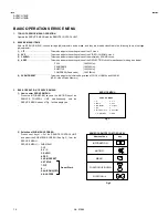
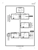
Page 14: ...UBTITLE 100 120Hzi COMPRESS Fixed value 100 120Hzi 5 5 VSM PRESET This mode adjusts the initial setting values of COOL NORMAL and WARM VSM Video Status Memory 3 BASIC OPERATION OF SERVICE MENU 1 How to enter SERVICE MENU Press the INFORMATION key and the MUTING key of the REMOTE CONTROL UNIT simultaneously and the SERVICE MENU screen of Fig 1 will be displayed 2 Selection of SUB MENU SCREEN Press ...

Page 15: ... COR LO 10 A NGLE 11 B OW 12 V S CR 13 V LIN IF SER VICE MENU 1 VCO 2 ATT ON OFF 1 2 SELECT i EXIT SERVICE MENU 1 IF 2 V C 3 AUDIO 4 DEF 5 VSM PR ESET 6 STAT US 7 PIP OFF 8 9 SHIPPING O FF 0 BUS F REE 1 9 SELECT EXIT i 1 ERR L IMIT 2 A2 ID T HR AUDIO 3 AUDIO 1 ERR LIMIT 10H C_AD_BITS STORE i EXIT OK 1 IF VCO CO OL NO RMAL W AR M 5 VSM PRESET VSM PRESET NO RMA L 1 CONT STORE i EXIT OK 1 CONT 2 BRIG...

Page 16: ... one from 2 V C 3 AUDIO 4 DEF and 5 VSM PRESET FUNCTION UP DOWN Key Select setting items FUNCTION Set adjust the setting values of the setting items MENU Key Memorize the setting value Before storing the setting values in memory do not press the CH TV POWER ON OFF key if you do the values will not be stored in memory INFOMATION Key Return to the SERVICE MENU screen 3 Can not setting 6 STATUS 7 PIP...

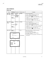
Page 17: ...lunteer Remote control unit CRT anode Chassis GND 1 RGB BLK 1 Receive a any broadcast 2 Push the ZOOM key and select the FULL mode 3 Select 2 V C from the SERVICE MENU 4 Select 1 RGB BLK with function UP DOWN key 5 Press the function key to find the cut off screen Black screen 6 Connect a DC voltmeter to CRT ANODE and chassis GND 7 Make sure that the voltage is DC 31 0kV 8 Press the function key t...

Page 18: ...and stop where the CLOW status changes 1 to 0 CLOW control loopout of window VSM PRESET ADJUST SETTING Item Measuring instrument Test point Adjustment part Description Setting of VSM PRESET Remote control unit 1 CONT 2 BRIGHT 3 SHARP 4 COLOUR 5 HUE 6 WDR R 7 WDR G 8 WDR B 1 Select 5 VSM PRESET from the SERVICE MENU 2 Select COOL with the MENU key of the remote control unit 3 Adjust the FUNCTION UP...

Page 19: ...s The setting values which adjust the screen to the optimum condition can be different from the initial setting values Setting item Adjustment item Initial setting value 2 V C PAL SECAM NTSC 1 RGB BLK 2 WDR R 0 3 WDR G 0 4 WDR B Do not adjust 12 5 BRIGHT 0 6 CONTRAST 0 7 COLOUR 0 0 0 8 HUE 20 9 SHARP Do not adjust 7 11 VID AGC Do not adjust 0 12 SYC SLI 7 13 A MOVIE 1 ...

Page 20: ...hite balance is good Adjustment of SUB BRIGHT Remote control unit 5 BRIGHT 1 Receive any broadcast 2 Select 2 V C from the SERVICE MENU 3 Select 5 BRIGHT with the FUNCTION UP DOWN key 4 Set the initial setting value with the FUNCTION key 5 If the brightness is not the best with the initial setting value make fine adjustment until you get the best brightness 6 Press the MENU key and memorize the se...

Page 21: ...set value make fine adjustment until you get the best colour 6 Press the MENU key and memorize the set value SECAM COLOUR SECAM COLOUR 1 Receive a SECAM broadcast 2 Make fine adjustment of SECAM COLOUR in the same manner as for above NTSC 3 58 COLOUR 1 Input a NTSC 3 58MHz COMPOSITE VIDEO signal from the EXT terminal 2 Make similar fine adjustment of NTSC 3 58 COLOUR in the same manner as for abov...

Page 22: ...et the initial setting value of SECAM COLOUR with the FUNCTION key 3 Adjust SECAM COLOUR and bring the value of A in the illustration to the values as shown given billow Voltage difference between white W and blue B 4 Press the MENU key and memorize the setting value NTSC 3 58 COLOUR 1 Input a NTSC 3 58MHz COMPOSITE VIDEO signal full field colour bar with 75 white from the EXT terminal 2 Set the i...

Page 23: ... HUE 1 W hen NTSC 3 58 is set NTSC 4 43 will be automaticallyset at the respective values 8 HUE Method of adjustment using measuring instrument NTSC 3 58 HUE NTSC 3 58 HUE 1 Input a NTSC 3 58MHz COMPOSITE VIDEO signal full field colour bar with 75 white from the EXT terminal 2 Select 2 V C from the SERVICE MENU 3 Select 8 HUE with the FUNCTION UP DOW N key 4 Set the initial setting value of NTSC 3...

Page 24: ...000 0000 0000 7 COR PIN Corner Pin 005 0000 002 0000 8 COR UP Corner Pin correction Up side 003 004 005 0000 9 COR LO Corner Pin correction Low side 007 003 002 0000 10 ANGLE Angle correction 0000 0000 0000 0000 11 BOW Bow shaped distortion correction 0000 0000 0000 0000 12 V S CR Do not adjust Vertical height correction 007 0000 013 0000 13 V LIN Do not adjust Vertical Linearity 003 002 0000 0000...

Page 25: ...ey and memorize the set value Adjustment of V SIZE 2 V SIZE 7 Receive a cross hatch signal 8 Select 2 V SIZE and set the initial setting value 9 Adjust V SIZE and make sure that the vertical screen size of the picture size is in the bellow table 10 Press the MENU key and memorize the set value 11 Input a NTSC VIDEO signal 60Hz from the EXT terminal and make sure that the vertical screen size is in...

Page 26: ...reen size of the picture size is in the bellow table 20 Press the MENU key and memorize the set value 21 Input a NTSC VIDEO signal 60Hz from the EXT terminal and make sure that the horizontal screen size of the each ASPECT mode is in the below table 22 Press the MENU key and memorize the set value Adjustment of EW PIN 6 EW PIN 23 Select 6 EW PIN and set the initial setting value 24 Adjust EW PIN a...

Page 27: ... 32 Set the initial setting value of COR UP with the FUNCTION or key 33 Adjust COR UP and bring the straight line at the upper corner 34 Select 9 COR LO with the FUNCTION UP DOWN key 35 Set the initial setting value of COR LO with the FUNCTION or key 36 Adjust COR LO and bring the straight line at the low corner 37 Press the MENU key and memorize the set value 38 If the extream upper lower corners...

Page 28: ...value of 13 V LIN with the FUNCTION key 49 Select 12 V S COR with the FUNCTION UP DOWN key 50 Set the initial setting value of 12 V S COR with the FUNCTION key 51 Adjust 13 V LIN and 12 V S COR so that the spaces of each line on TOP CENTER and BOTTOM become uniform NOTE Do not adjust PANORAMIC SUBTITLE mode At first the adjustment in 100Hz FULL mode should be done then the data for the other aspec...

Page 29: ...ouch 3 AUDIOadjustment of the SERVICE MENU as it requires no adjustment If values had changed for the some reason set the initial values in the following table 3 AUDIO Do not adjust Setting item Variable range fixed value 1 ERR LIMIT 00H FFH 0AH 2 A2 ID THR 00H FFH 19H ...

Page 30: ...OUT R L POWER BASS LPF M_CV Y VTV1 TV OUT L TV RTV V1 L1 R1 YS SLOW1 V2 C2 R2 L2 OUT R2 OUT V2 OUT V3 Y3 C3 L3 R3 63 AV SW PWB M_C REMOCON S KEY 1 2 REMOCON RECEIVER FRONT CTRL PWB SDA2 SCL2 MICON PWB D931 T901 Q521 H OUT IC401 V OUT B1 FOCUS1 FOCUS2 EHV SCREEN IC402 EW V DRIVE H OUT SDA1 SCL1 100Hz PWB V DY H DY POWER DEF PWB B CRT VM COIL CRT SOCKET PWB SP R IC203 B OUT IC202 R OUT IC201 G OUT F...

Page 31: ...EY2 VD KEY3 REMOCON H P_DET TIMER_LED POW_ON OFF POW_ON OFF OSD_YS TU2_SW1 AGC TU2_SW0 TU2_AFC TU2_SW1 A_SUB_GND H P_L H P_GND SUBTITLE R_SUB A_SUB_GND R_SUB BBE_ON OFF H P_R H P_L BBE_BOOST YS2 S_CV TU1_AFC AV_LINK DATA MSP_RESET H P_GND SCL2 SDA2 SCL2 SDA2 H P_R YS2 AFC2 POW_ON OFF SCL1 TXT_CV AUDIO_MUTE YS2 AFC2 OSD_R AMP_MUTE CLOCK ECO_LED POW_ON OFF SDA1 SCL1 AV_LINK TU2_SW0 A MUTE SCP U100 Y...

Page 32: ...C637 X R622 X Q614 X C620 X R624 X R625 X R628 X IC602 X R621 X R653 X C608 X C619 X R630 X R641 X R629 X Q608 X C624 X C625 X R626 X C645 X R627 X D622 X R652 X D606 X C636 X D625 X C655 X D607 X D623 X D624 X C623 X C644 X R640 X D618 X D603 X D608 X R613 X R614 X R615 X C609 X MUTING Q613 X R616 X Q610 X R612 X Q609 X HS603 X R611 X INV Q611 X CN111 X C656 MSP3415DQGB3GHX MULTI SOUND PROCESSOR ...

Page 33: ...3 D541 3 3 OMF 1W R464 10k 1 R472 0 1 QCZ0120 104Z C464 H OUT 2SC5552 RL Q521 0 22 TF C503 0 011 QFZ0200 113 C522 5 6 1 2W R506 1 5k 1 2W R503 12k R502 EU2 T3 D552 100 16 QETN1CM 107Z C581 MY 560p 500 QCB32HK 561Z C555 X C915 X R466 X C504 V11CA C1 D521 1100p 1800VH QFZ0122 112 C521 BW R467 10 250 QEZ0472 106Z C461 2SA1208 ST Z1 T Q581 CEHP00N 001Q HS461 470 R501 1SS81 T5 D501 CE41832 001 K523 BSN...

Page 34: ...4 No 51944 7 AV28CH1EUS AV28CH1EUB AV28CH1EUS AV28CH1EUB 2 11 2 12 100Hz PWB CIRCUIT DIAGRAM 100Hz PWB SMF0Z005A U2 DEFFERENCE LIST V103BD SMF 0Z005A U2 SMF 0Z005A U2 SMF 0Z005A U2 SMF 0Z005A U2 SMF 0Z005A U2 ...

Page 35: ...3 0 R098 220 R158 1 5 L022 0 K003 0 K005 B B B B B D11 D3 D4 D10 D12 D2 A4 RD CSROM CKE CSSDRAM A15 A14 A13 A0 A1 A2 A3 A8 AA19 A8 A9 A10 A11 A12 A13 A14 A15 AA16 A0 D15 D15 D7 D14 D6 D13 D5 D12 D4 AA18 AA17 A7 A6 A5 A4 A3 A2 A1 D14 CSROM RD D0 D8 D1 D9 D2 D10 D3 D11 D13 D12 D11 D10 D9 D8 UDQM CLK CKE A9 A8 A7 A6 A5 A4 A3 A2 D0 D1 D2 D3 D4 D5 D6 D7 LDQM WR A15 A14 CSSDRAM A11 A10 A0 A1 AFC1 AFC2 A...

Page 36: ...716 001Z L012 X Y007 QMS3004 C01 HEADPHONE JACK J001 1k R021 X R007 0 1 NCB31CK 104X C021 47 25 QETN1EM 476Z C022 X Y008 0 Y009 1k R008 68P NDC31HJ 680X C005 3 LED SW Q003 220 R005 1k R022 330 R039 2 D011 4 LED SW Q002 QSW0619 003Z S003 QSW0619 003Z S002 QSW0619 003Z S001 T3 15AH QMF51D2 3R15J1 F901 QSW0824 001 S901 CHGH0001 0H N CN00W 3 LED SW Q004 CN0PW POWER CORD QMPK160 185 JC QQR1095 003 LF90...

Page 37: ...6 2 7k R225 SK001 EU01N T2 D205 100k QRL029J 104 R230 0 1 QFK62EK 104Z C211 470k 1 2S R239 10k R227 0 1 NCF31CZ 104X C205 2 7k R224 12k R101 10 250 QETN2EM 106Z C221 X R238 CH C201 100k QRL029J 104 R229 0 1 QFK62EK 104Z C210 BW R240 47 25 C207 X C217 180p CH C214 EU01N T2 D204 X D302 33 250 QETM2EM 336 C218 TP 47B TP E 0 022 MM QFZ0097 223 C219 H H H CN0SC 4 7k R104 1 5k 1 2S QRC121K 152Z R235 2 7...

Page 38: ...06 0 0047 C105 0 0047 C106 0 0047 C108 J001 75 R108 0 0047 C109 0 0047 C110 QQR0716 001Z L101 SC_B1 R1 SC_G1 SDA2 AV_LINK M_CV Y L1 SDA2 SCL2 V2_OUT SC_R1 M_C V2 Y2 SDA2 SCL2 V3 Y3 AV_LINK C2 SC_YS1 SCL2 R2 SLOW2 SLOW1 V4 RTV1 C3 L3 SLOW3 L2 R3 R1 TV_OUT SC_YS1 SLOW1 V1 V2_OUT 9V SLOW2 L2 R4 C3 L3 L4 L1 V2 Y2 TV_OUT V4 SC_G1 SC_B1 L4 R2_OUT L_SUB Y4 C4 R_SUB R4 Y4 R2 L2_OUT A MUTE L_SUB C4 R_SUB S...

Reviews: