No. 51944
AV28CH1EUS
AV28CH1EUB
17
ADJUSTMENTS
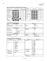
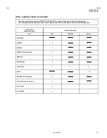
CHECK ITEM
Item
Measuring
instrument
Test point
Ad justment part
Description
Check of B1
Power Supply
Signal
generator
DC voltmeter
Remote
control unit
TP-91(B1)
TP-E(
#
#
#
#
)
[X connector
on POWER
DEF PWB]
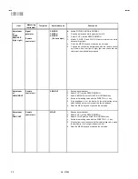
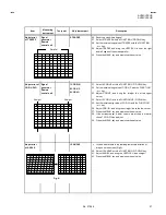
1.RGB BLK
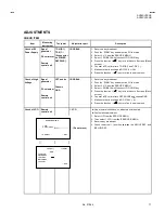
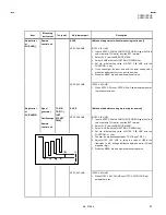
1. Receive a any broadcast.
2. Push the “ZOOM” key and s elect the FULL mode.
3. Select 2. V/C from the SERVICE MENU.
4. Select 1. RGB BLK with function UP / DOWN key.
5. Press the fu( ) key to find the cut off screen (Black
screen).
6. Connect a DC voltmeter to TP-91(B1) and TP-E(
#
).
7. Make sure that the voltage is DC139.9
±
2.0V.
8. Press the function – ( ) key to return to s ervice menu..
Check of High
Voltage
Signal
generator
DC volunteer
Remote
control unit
CRT anode
Chassis
GND
1.RGB BLK
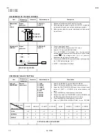
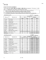
1. Receive a any broadcast.
2. Push the “ZOOM” key and s elect the FULL mode.
3. Select 2. V/C from the SERVICE MENU.
4. Select 1. RGB BLK with function UP / DOWN key.
5. Press the fu( ) key to find the cut off screen (Black
screen).
6. Connect a DC voltmeter to CRT ANODE and chassis GND.
7. Make sure that the voltage is DC 31.0kV .
8. Press the function – ( ) key to return to s ervice menu.
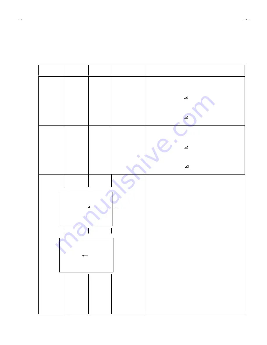
Check of VCO
Remote
control unit
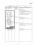
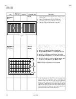
1. VCO
"
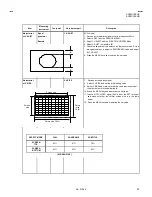
Under normal c onditions, no adjustment is required.
"
Confirmation adjustment.
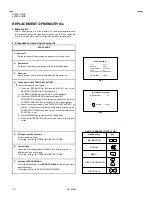
1. Select 1.IF from the SERVICE MENU.
2. Then select 1.VCO from the IF SERVICE MENU.
3. Receive any broadc ast.
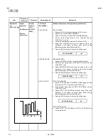
4. Check
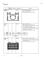
the arrow ( ) position between the ABOVE REF. and
BELOW REF.
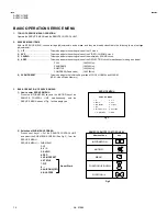
+1kV
-1.5kV
TOO HIGH
ABOVE REF
JUST REF
BELOW REF
TOO LOW
i : EXIT
VCO(CW)
****
MHz
MAIN
1. VCO
2. ATT ON/OFF
i : EXIT
IF SERVICE MENU
1-2 : SELECT
(Do not move)

